Support Structure and Type Definitions
In SolidSupport, each support assembly is defined as a combination of multiple child supports. Among those child supports, exactly one is treated as the master support. During the creation process, the first support that is added becomes the master support by default, while later additions are treated as child supports. The master-child relationship can still be adjusted after the assembly is created.
SolidSupport separates supports into regular supports and reference-type supports. Regular supports can be placed directly on the pipe, such as U-bolts and pipe shoes. Reference-type supports cannot be placed directly on the pipe, such as guide structures attached to a shoe or anchor plates on a concrete floor. A reference-type support can only be added as a child support attached to a master support, which avoids leaving that structure as a logically invalid standalone object.
Create a Master Support from the Indexed Selection View
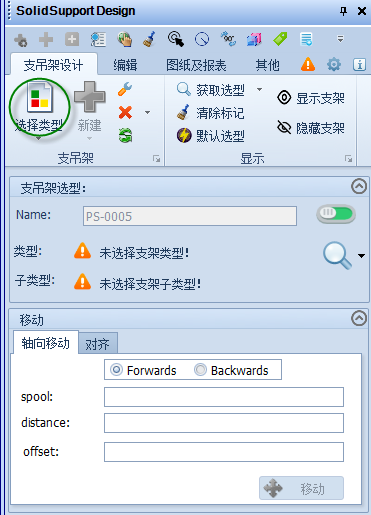
(1) Click the Select Type button to enter the type-selection interface.
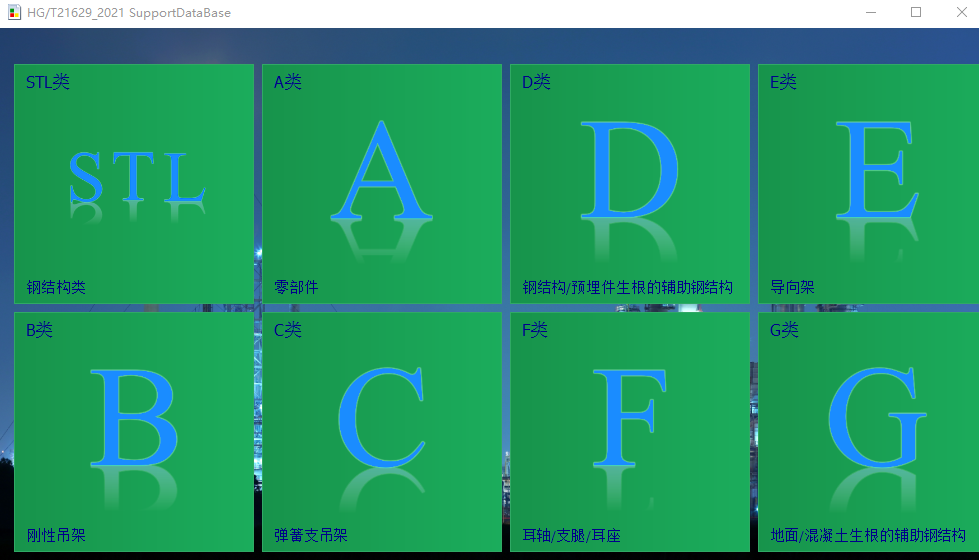
(2) Choose a support family and double-click to enter the support-selection step.
Inside the type-selection interface, the mouse wheel can be used to scroll through support families quickly.
(3) Select a support and confirm it with a double-click.
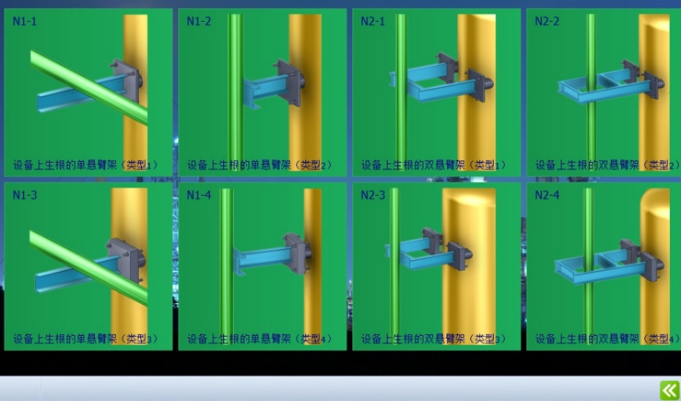
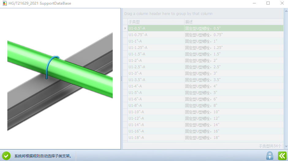
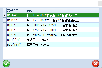
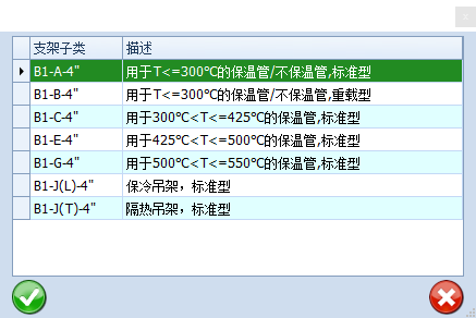
(4) Select the subtype, click the confirmation check mark, and close the window. If matching rules have already been configured, the interface may be locked as shown on the right, in which case no manual subtype selection is required.
If no matching rule is available, the designer must choose the support subtype manually.
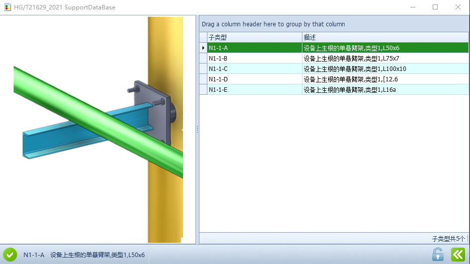
If matching rules do exist, the subtype list is filtered according to that preset logic and you can confirm directly without choosing manually.
(5) Review the selected configuration if needed. This step can be skipped.
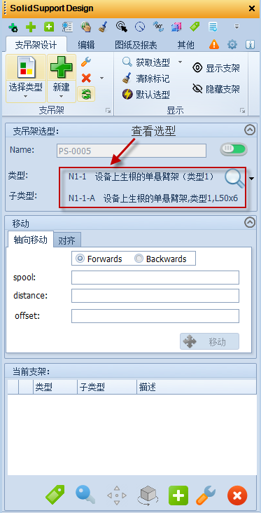
(6) Click the Create New button to begin creation.
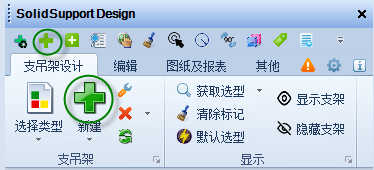
(7) Snap to a pipe, elbow, or another supported model object to generate the support. If the matching rules produce multiple child-item options, a child-item selection window appears; otherwise the support is generated directly.
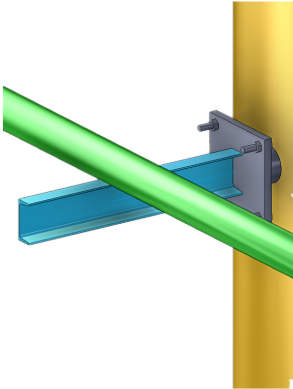
(8) The model is created.
Create a Master Support from the List View
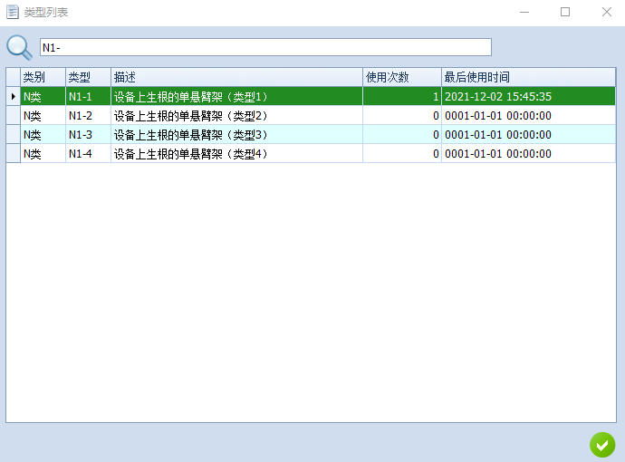
(1) Click the List Selection button to enter the list-based selection interface.
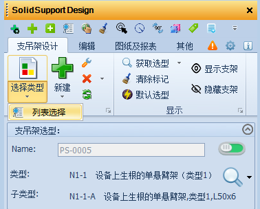
(2) Enter the support name, choose the support, and confirm with the check mark. This window also shows usage frequency and the last-used timestamp, so recently used supports can be surfaced first in later filtering.
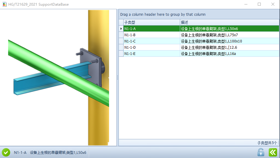
(3) Select the subtype, click the check mark, and close the interface. If matching rules are configured, the interface may already be locked and no manual choice is needed.
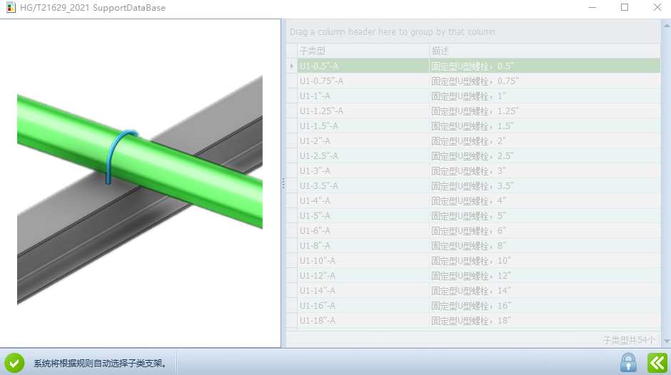
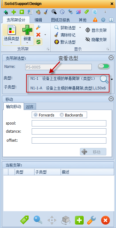
(4) Review the selection if needed. This step can also be skipped.
(5) Click the Create New button to start creation.
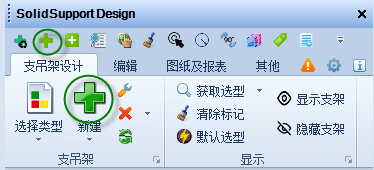
(6) Snap to a pipe, elbow, or another supported object to generate the support. If multiple child items match, a child-item chooser will appear; otherwise the support is generated directly.
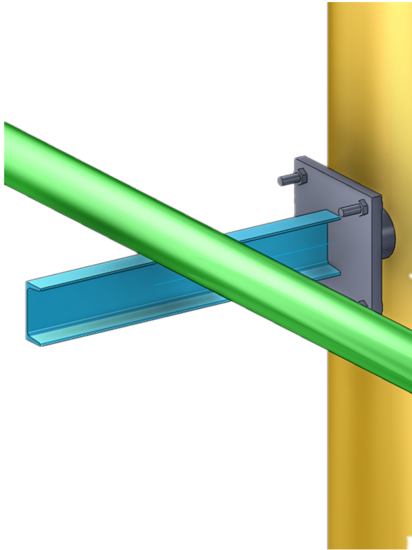
(7) The model is created.
Add a Child Support
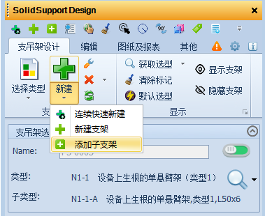
The selection steps for a child support are the same as those for a master support. After completing the selection, click the existing support entity in the model instead of snapping to the pipe again, then click the add-child-support command to generate the child support and edit its parameters.
Modify Support Parameters
(1) Select the support you want to edit and click the modify command. If a support assembly contains multiple child supports, the child support highlighted in green is the one currently selected. A support with a small key icon after its name indicates the master support.
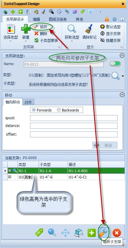
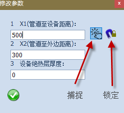
(2) Modify the design parameters and confirm with the check mark. Note that the snap option can capture model geometry to populate values instead of entering them manually, and supports with intelligent sensing can lock parameters here.
Move a Support
(1) Move the full support assembly.
Move the ATTA point and the physical support follows automatically. Do not move the physical support directly.
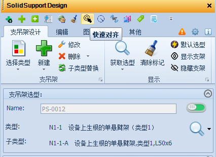
For quick alignment, click the Quick Align command and snap to model geometry. This allows the support to move axially and align with the selected object.
(2) Move a child support.
Select the child support first, then click the Move Child Support command to enter the child-support movement interface.
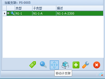
Enter the movement distance and click Move to shift the support by that amount.
Rotate a Support
(1) Rotate the full support assembly.
Rotate the ATTA point and the physical support follows automatically. Do not rotate the physical support directly.
For quick rotational alignment, click the Rotate Align command and snap to model geometry so the support can rotate toward the center point of the selected object.
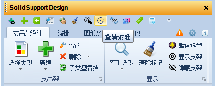
(2) Rotate a child support.
Select the child support first, then click Rotate Child Support to open the child-support rotation interface.
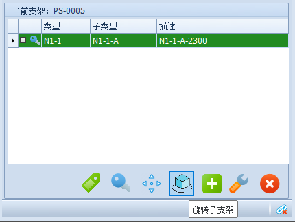
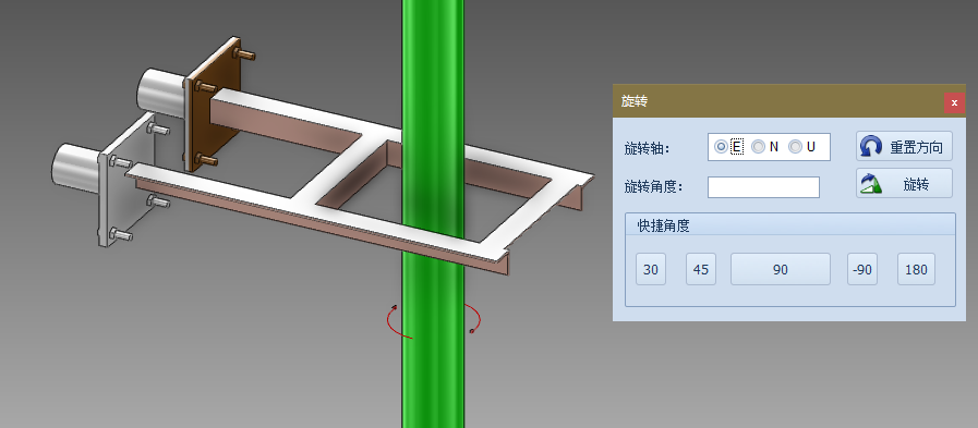
Select the rotation axis, use the directional indicator in the model for reference, enter a rotation angle, and click Rotate. You can also pick one of the preset quick-angle options directly.
Delete a Support
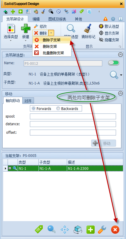
(1) Delete only a child support.
Select the child support to remove and click Delete Child Support. If one support assembly contains multiple child supports, delete the child support first and only then delete the master support. The button shown here  can promote any child support to become the master support.
(2) Delete a single support assembly.
Method 1: delete the ATTA object in the model and the support geometry is removed automatically.
Method 2: select the support geometry to remove, click the command button, and delete both the support entity and its corresponding ATTA entry together.
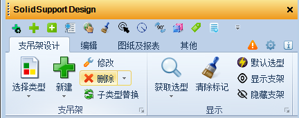
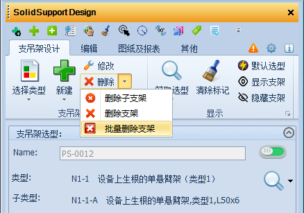
(3) Delete support assemblies in batch.
Method 1: delete the related ATTA objects in the model and the support geometry is removed automatically.
Method 2: click the batch-delete command, select the support entities to remove according to the prompt, press ESC to open the confirmation window, then confirm deletion of the selected support entities and their related ATTA entries.
Design Output and Material Summary
(1) Preview the isometric drawing output.
Support assemblies created through the SolidSupport workflow can express support numbering clearly on ISO drawings. During construction, the support can be treated like a special piping component and installed according to its position in the isometric drawing.
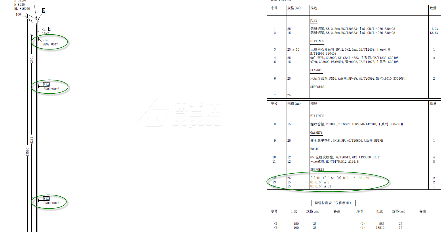
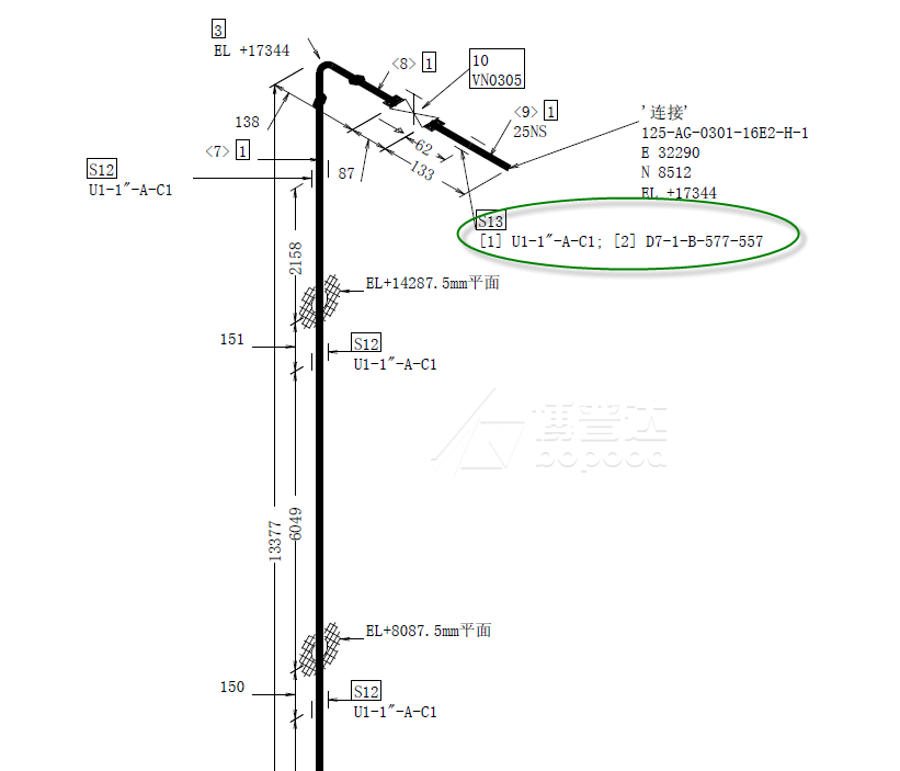
(2) Preview the material summary output.
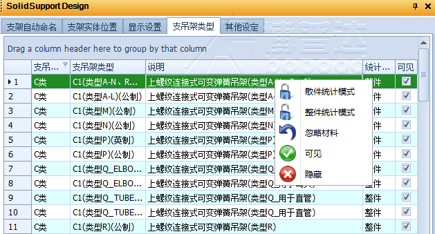
Material summary output is divided into two categories: loose-part summary and packaged-support summary. Loose-part summary treats each combined part inside the support as a material-counting element, while packaged-support summary treats the full support assembly as the counting unit and supports full-package purchasing.
Under the logic of the newer standard, packaged support procurement is gradually becoming the mainstream approach as long as the critical dimensions, load requirements, and support performance still meet design needs. Even so, in practical procurement, design, and construction work, some support types such as trunnion-style supports, simple plate-based supports, and auxiliary steel structures may still be better counted as loose parts. Their dimensions can then be cut on site, while total-length statistics remain easier for procurement and material pickup.
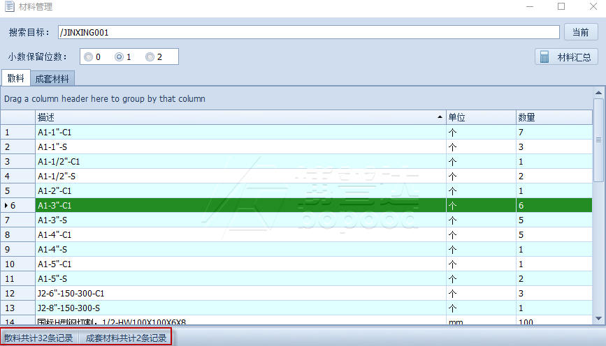
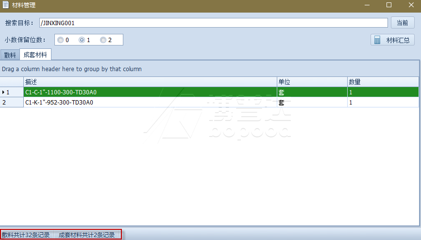
The switch between loose-part and packaged-support summary can be configured by the user. One important note is that for some support types, loose-part and packaged-support output are effectively the same because the support is designed and procured as one full unit. The figure below shows that case.