Preface
SolidSupport is a 3D pipe support/hanger entity program developed by Chengdu Bopood Technology Co., Ltd., compatible with PDMS, E3D, S3D, AM, and certain domestic software. It integrates Bopood's self-developed support/hanger engine and innovatively uses a parameter-driven approach to build the support/hanger database. Through a powerful back-end management system, users can customize any type of support/hanger. SolidSupport features fast customization, high flexibility, ease of use, complete material information, and a high degree of intelligence.
SolidSupport consists of two major modules: support/hanger design and support/hanger database management. The support/hanger design module is used by support/hanger designers. In this module, users create supports/hangers in the design project, perform modifications and positioning, and deliverables such as support detail drawings, material takeoff lists, and support schedules.
This document is a user tutorial for the support/hanger design module, demonstrated on the Hexagon Smart Plant 3D (S3D) 3D design platform. This tutorial applies to SolidSupport_V2.2 series versions. For technical support, please contact Chengdu Bopood Technology Co., Ltd. through the official website (www.bopood.com).
Interface
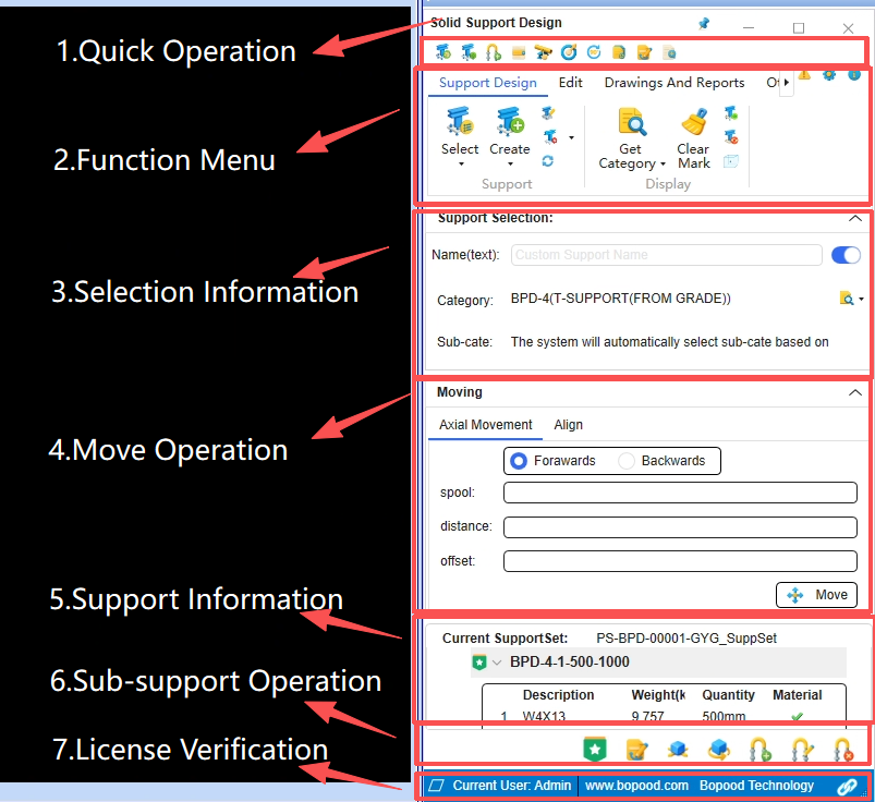
The default main interface of the SolidSupport support/hanger design module is divided from top to bottom into seven areas: Quick Access, Function Menu, Selection Info, Move Operations, Support Info, Sub-support Operations, and License Verification.
Licensing
To apply for a trial, please visit the Chengdu Bopood Technology Co., Ltd. official website (www.bopood.com) to obtain contact information for technical support. Without a license, up to 100 supports/hangers can be added per project.
The SolidSupport_V2.2 series license consists of two parts: the SolidSupport 2.2 Assistant and the SolidSupport plugin.
Standalone License
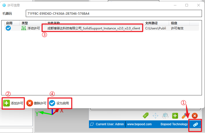
① Obtain Machine Code
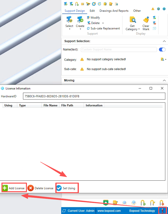
Click the button at the bottom-right of the SolidSupport 2.2 Assistant (or the button in the License Verification area of the SolidSupport plugin) to view license information and obtain the device machine code. Send the machine code to technical support to receive the license file.
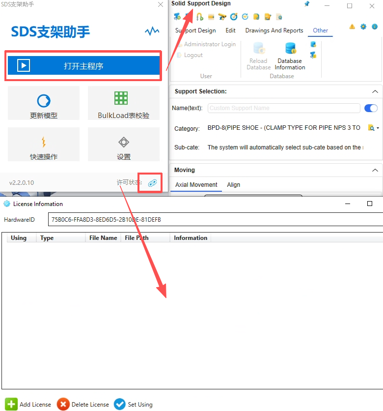
② Load License
The zip package sent by technical support contains two license files, which must be loaded separately by the SolidSupport 2.0 Assistant and the plugin (the machine code shown in the figure is for illustration only).
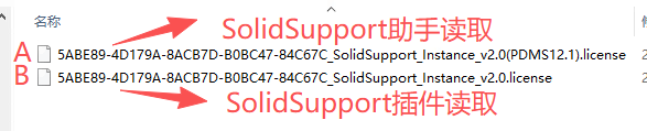
SolidSupport 2.2 Assistant: Add License A and set it to enabled.
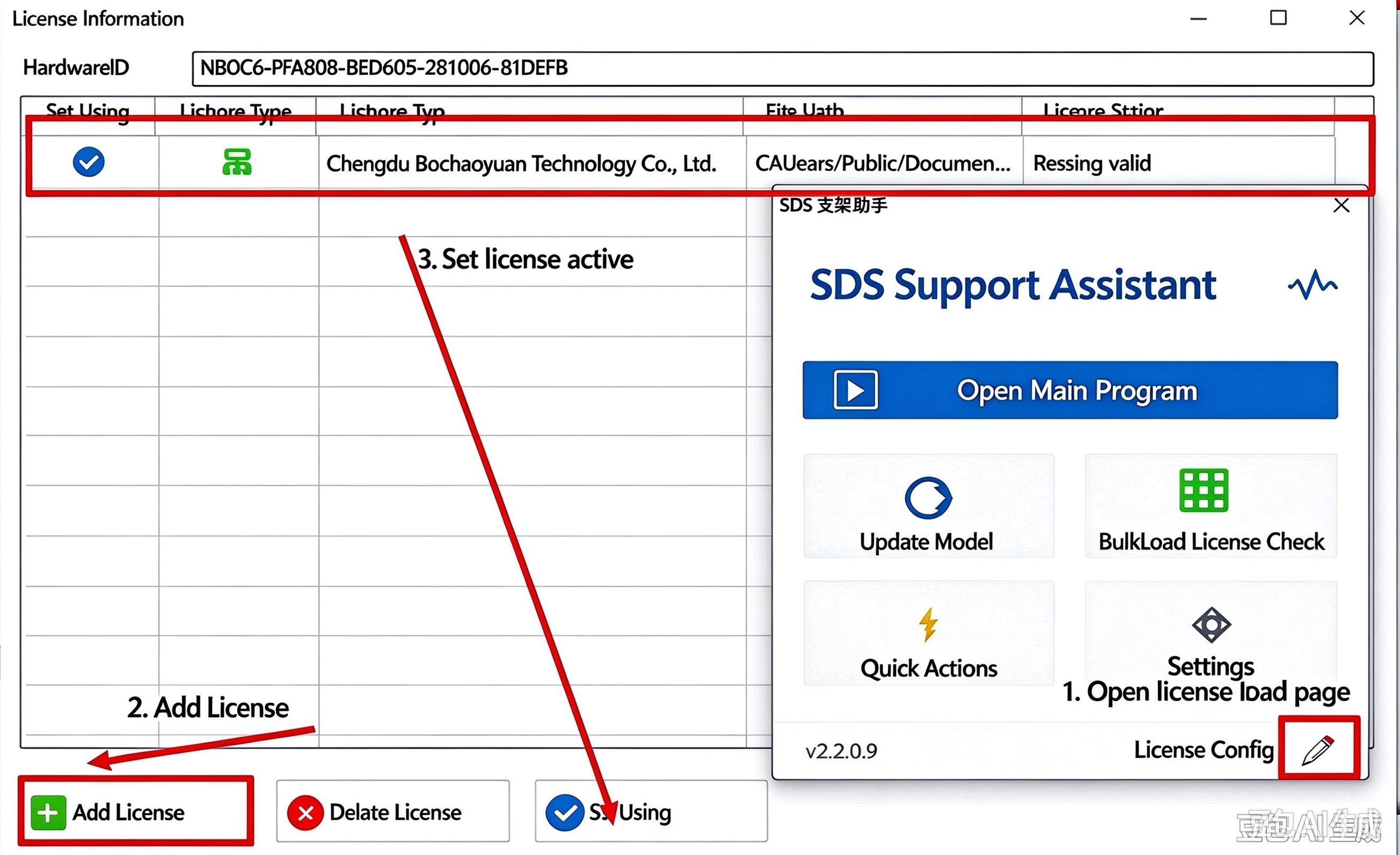
SolidSupport plugin: Add License B and set it to enabled.
Floating License
For floating licenses, one computer must serve as the license server (with a stable network). Computers on the same LAN connect to the server to obtain licenses.
① Install License Manager
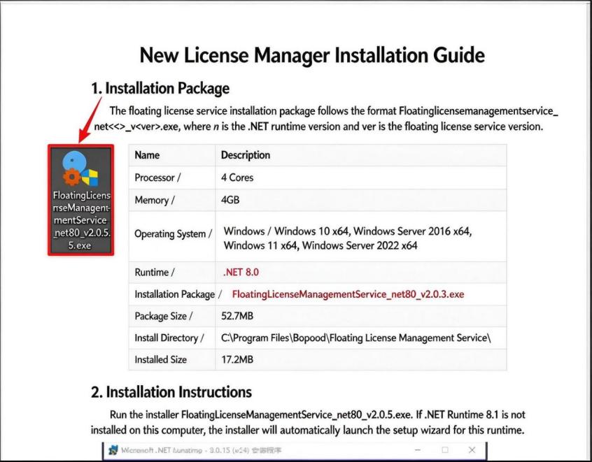
The Floating License Management Service must first be installed on the server computer. See the "New License Manager Installation Guide" for instructions.
② Obtain Machine Code and IP Information
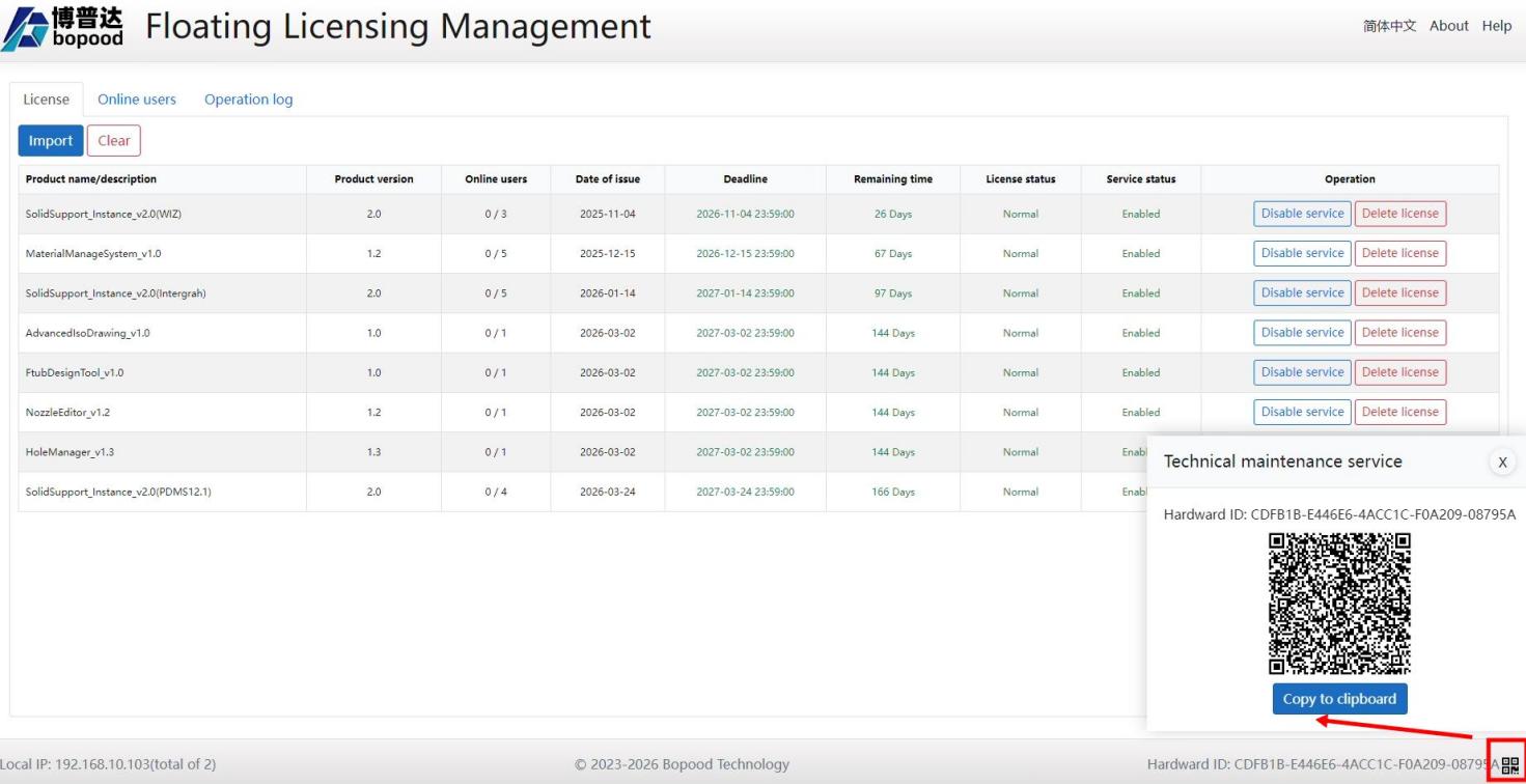
After installation, double-click the icon to open the license management interface, scan the QR code, and send the recognized content to technical support to obtain the license.
③ Load License
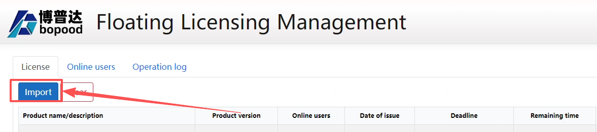
The zip package sent by technical support contains four license files, which must be loaded separately on the server and the client. Server licenses are in the red box below; client licenses are in the green box.

Server: Directly import the two license files with the .server.flic extension.
Client:
Open the SolidSupport 2.0 Assistant, load the license file whose name contains (Intergraph), and set it to enabled.
Open the SolidSupport plugin, load the last license file, and set it to enabled.
Attributes and Concepts
Before proceeding with support/hanger design, it is necessary to understand certain attributes and concepts related to supports/hangers, including the necessary global variables, the relationship between attachment points and support entities, how support codes are generated, and where component information is stored.
Attributes
This section introduces the important attributes at different levels in the catalog tree.
Node
A node is the key carrier for marking the position of a support/hanger on a pipe. To display support/hanger information on the pipe isometric drawing, the attachment point attributes must be supplemented.
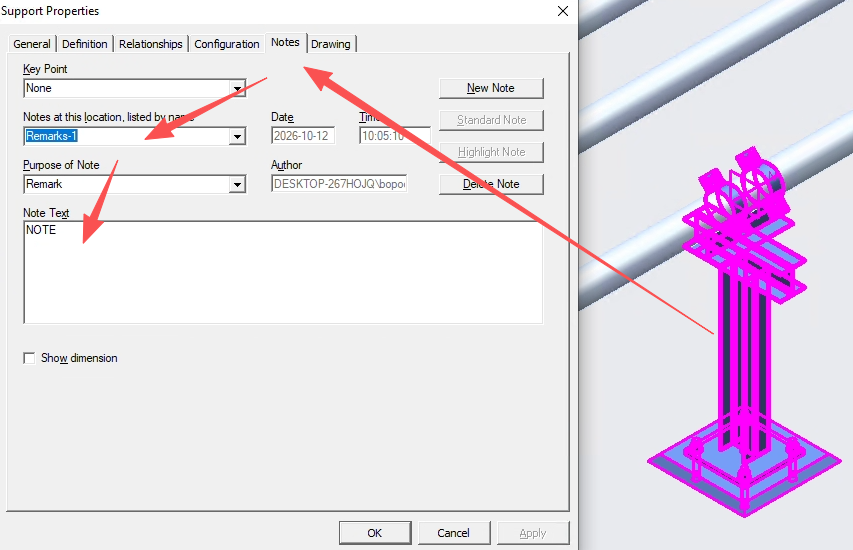
The drawing information on the isometric drawing is recorded in the Notes attribute at the Support level.
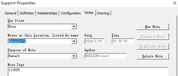
:SSTSupport
:SST_Support is the storage level for support/hanger groups, and has a one-to-one correspondence with attachment points. A support group contains at least one sub-support.
BOM Description: This attribute is the description (support/hanger code) of the support/hanger and cannot be modified.
:SSTSubSupport
:SST_SubSupport is the storage level for specific support/hanger types, belonging to :SST_Support (support group).
BOM Description: This attribute is the description (support/hanger code) of the support/hanger and cannot be modified.
:SSTCompSet
:SST_CompSet is the storage level for component sets. All parts that make up a support/hanger are stored under the component set, which belongs to :SST_SubSupport.
Combined Support
Multiple support types are combined in various ways and share a single node, belonging to the SST_Support level.
Reference Support
A reference support has a strong association with other support types. The support type associated with the reference support is called the referenced support. It belongs to the :SST_SubSupport level.
Main Support and Sub-support
Before adding a reference support, the referenced support must be added as the main support first, and then the reference support is added as a sub-support. Both the main support and sub-support belong to the :SST_SubSupport level.
3.2.4 Shared Support
Multiple support groups can be combined and share a single support serial number (distinguished by a [X/Y] suffix), belonging to the :SST_SuppSet level.
Select Type
There are two ways to select a type: image selection and list selection. Image selection allows viewing the appearance, combination form, and installation position of support types, and is suitable for designers unfamiliar with the support catalog. List selection allows quick selection of support types; frequently used supports are listed at the top by default.
Image Selection
(1) Click the Select Type icon in the Function Menu area to open the type selection interface.
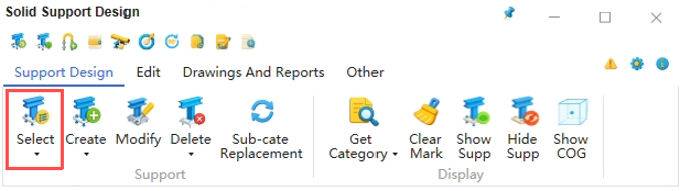
(2) In the type selection interface, select a support category and double-click to enter and choose a specific support type (alternatively, after selecting a category, click the Next button at the bottom-right). To return from the support type to the category, click the Back button at the bottom-right.
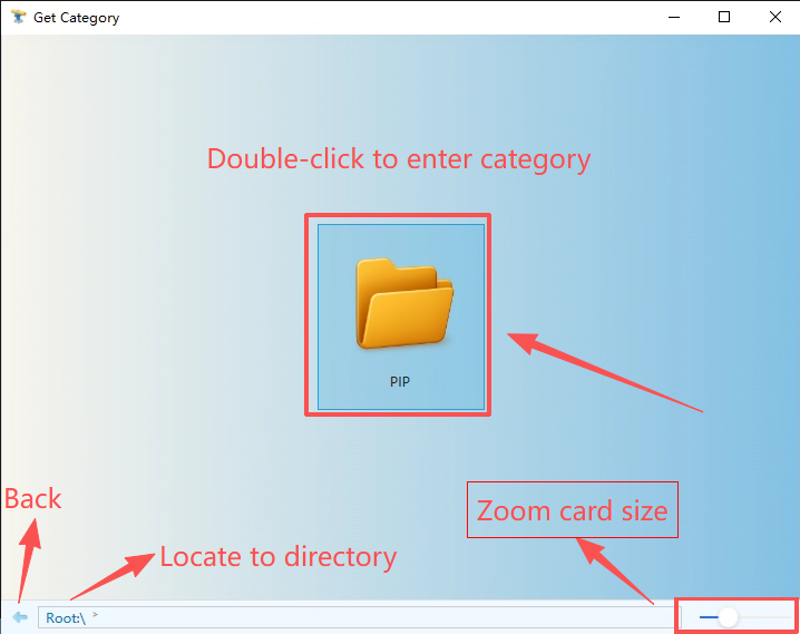
(3) Select a support type and double-click to enter and choose a sub-type (alternatively, after selecting the support type, click the Next button at the bottom-right).
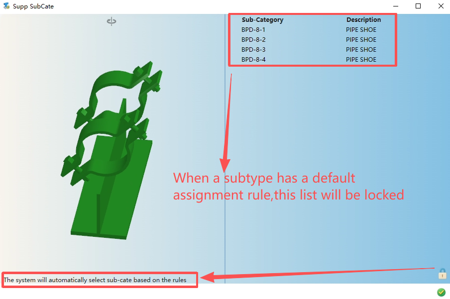
If a default matching rule exists, the sub-type selection interface is locked and the sub-type cannot be selected directly; in this case, simply click OK.
If no default matching rule exists, select a sub-type first and then click the OK button to complete the selection.
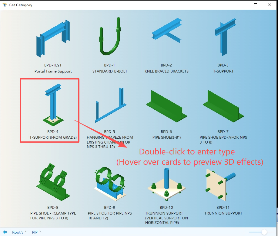
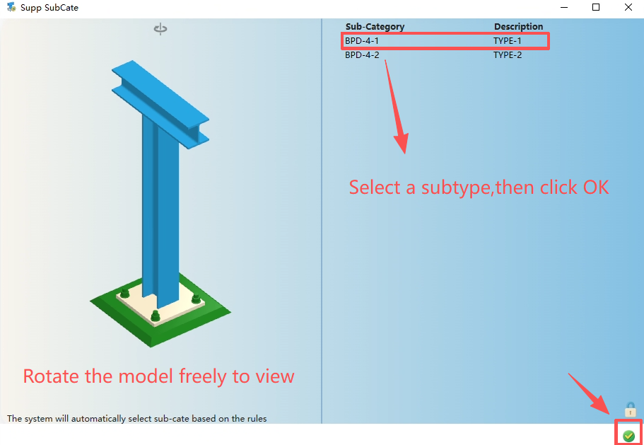
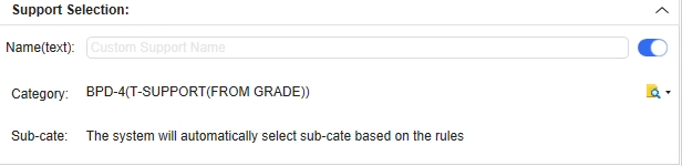
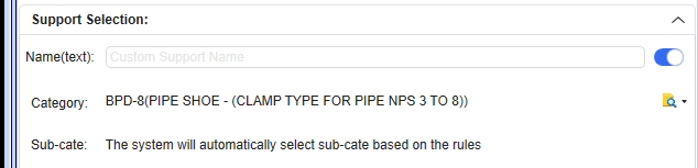
(4) The Selection Info area displays the currently selected support type and sub-type information.
List Selection
(1) Click the dropdown button of Select Type and choose List Selection to open the list selection interface. Alternatively, click the List Selection button in the Quick Access area.
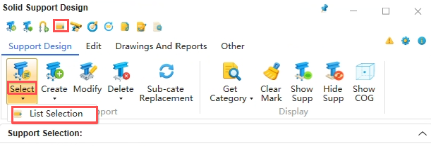
(2) In the list selection interface, you can search for support types. The search can be by type number (e.g., J2) or by type description (e.g., pipe shoe). Frequently used supports appear at the top; here you can also see the usage count and last-used time of each support type.
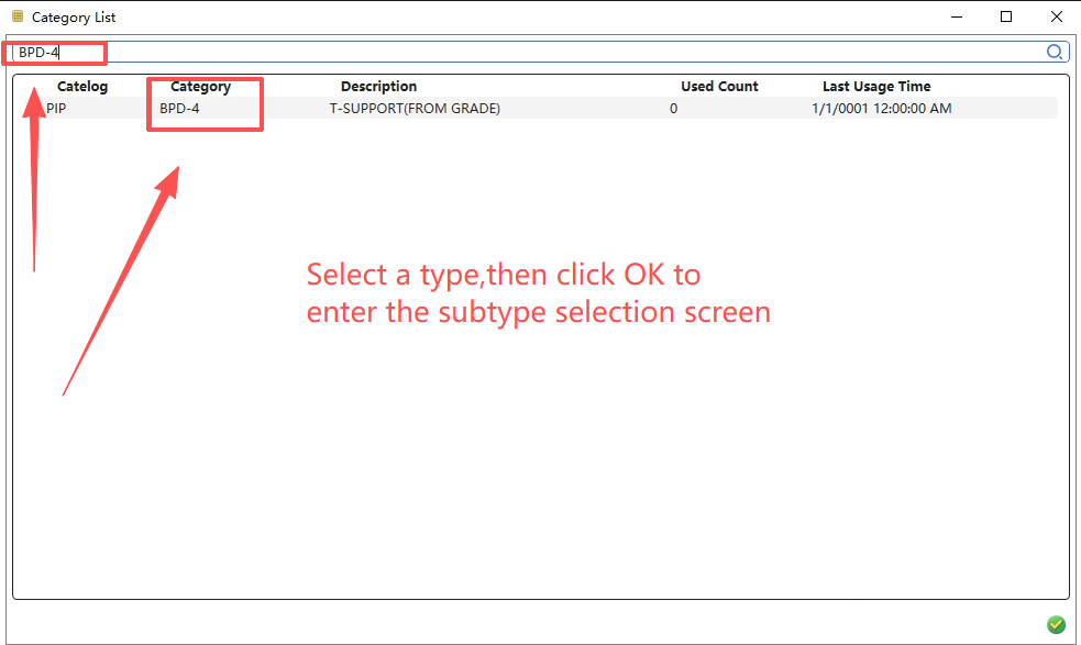
(3) Select a sub-type in the sub-type selection interface. If a default matching rule exists (the interface is locked and the sub-type cannot be selected), simply click OK.
(4) The Selection Info area displays the currently selected support type and sub-type information.
Create New
There are five ways to create supports/hangers: Create Support, Continuous Quick Create, Add Sub-support, Create Supports in Current Support Set, and Merge Support into Current Support Set. All SolidSupport supports/hangers are created based on pipes.
Since attachment points (each corresponding to a support group) must be created on pipes or fittings, new supports are created by clicking on pipes or fittings using the Create Support method. For combined supports, sub-supports are created using the Add Sub-support method after selecting the support type.
Create Support
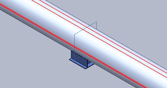
(1) Select the J1(Imperial) welded pipe shoe and click the Create button in the Function menu area (alternatively,click the Create Support button in the quick Access)
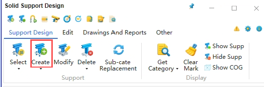
(2) Click on a pipe or fitting to generate the support/hanger.
Continuous Quick Create
(1) Select J1 (Imperial) welded pipe shoe, click the dropdown arrow of Create in the Function Menu area, and choose Continuous Quick Create (alternatively, click the Continuous Quick Create button in the Quick Access area).
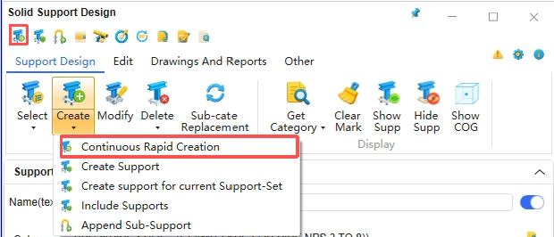
You can click on blank space to exit the Continuous Quick Create mode.
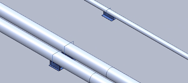
(2) Click continuously on pipes or fittings to generate supports/hangers (can span different pipe diameters).
Add Sub-support
When building a combined support that shares an attachment point, or when creating a reference support, supports must be created using the Add Sub-support method. Here, we use creating a T-support under a pipe shoe as an example.
(1) Select D12-1 T-support with sub-type D12-1-A. In the graphic interface, select the pipe shoe, click the dropdown arrow of Create in the Function Menu area, and choose Add Sub-support (alternatively, click the Add Sub-support button in the Quick Access / Sub-support Operations area).
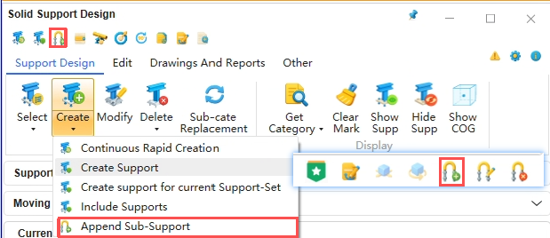
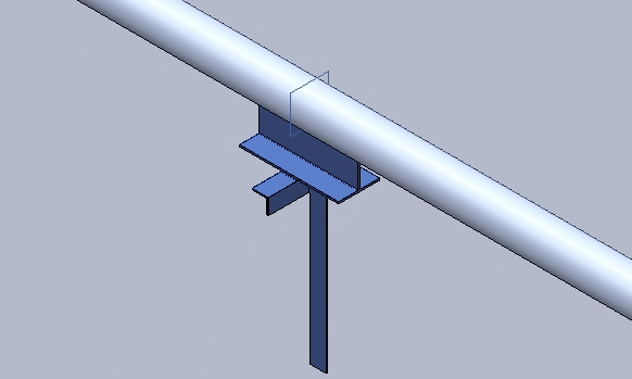
(2) In the graphic interface, the T-support is added below the pipe shoe.
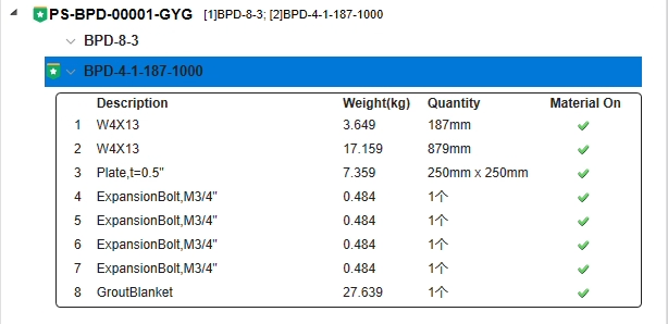
(3) In the Support Info area, you can see the type, description, and other details of both the pipe shoe and T-support, and can also view specific component information here.
4.2.4 Create Supports in Current Support Set
This function is for shared-support scenarios.
First create a J2 pipe shoe, then create G4 as a sub-support.
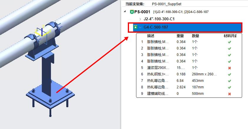
When we need to create on another pipe adjacent to this support, use the Create Supports in Current Support Set function.
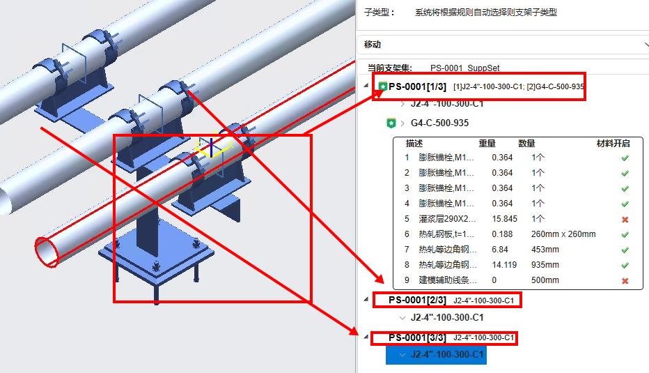
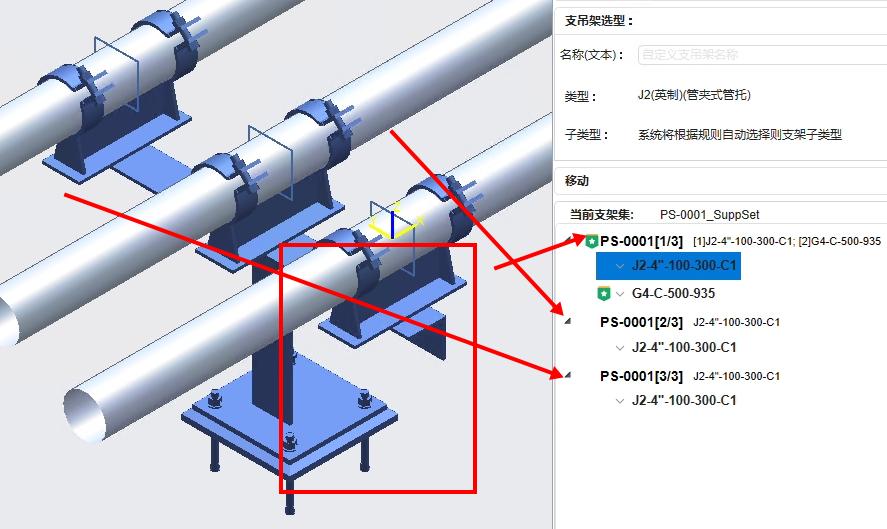
Supports on multiple pipes will be stored in one support set, and each support number will have a [X/Y] suffix to indicate the shared-support relationship.
4.2.5 Merge Support into Current Support Set
This function is for shared-support scenarios.
First create a J2 pipe shoe, then create G4 as a sub-support, and create another J2 pipe shoe on an adjacent pipe.
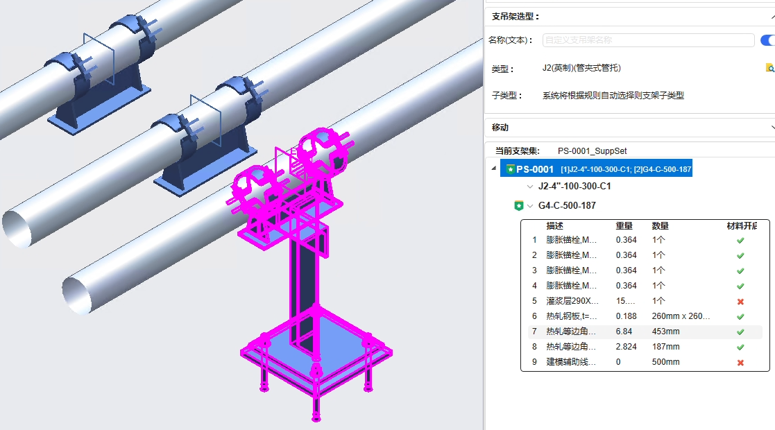
At this point each support is independent, and the secondary steel support serves only the pipe shoe on one pipe. When using Merge Support into Current Support Set, supports on all pipes will be stored in one support set, and each support number will have a [X/Y] suffix to indicate the shared-support relationship.
Move
Moving is for positioning support entities. SolidSupport provides two positioning methods: axial move and align. Using SolidSupport's built-in move function maintains consistency between the attachment point and the support entity position, preventing them from becoming disconnected.
Axial Move
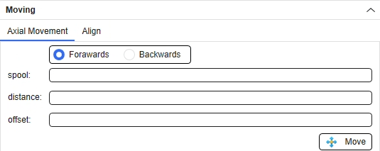
Axial move has three modes: spool, distance, and offset, each with Forwards and Backwards directions.
(1) spool: Forwards is the distance along the flow direction to the end face of the previous fitting; Backwards is the distance against the flow direction to the end face of the next fitting.
(2) distance: Forwards is the distance along the flow direction to the center point of the previous fitting; Backwards is the distance against the flow direction to the center point of the next fitting.
(3) offset: Forwards is the distance along the flow direction from the current position; Backwards is the distance against the flow direction from the current position.
Align
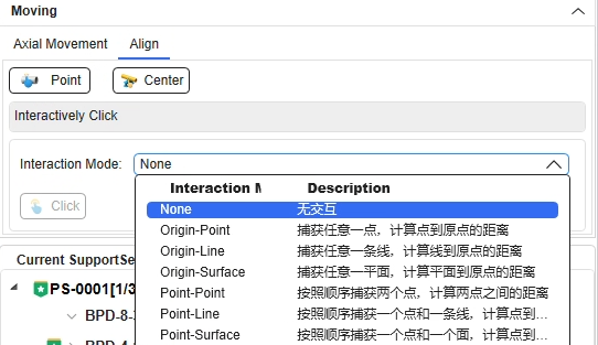
Align has three modes: click pipe, align to reference center, and interactive click.
(1) Click pipe: Align to any point on a straight pipe segment.
(2) Align to reference center: Align to the center point of any object. For example, after adding a pipe shoe, you can quickly align to the center of the beam.
(3) Interactive click: Align based on interactive selection.
Modify
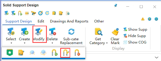
Modification is for setting parameters that cannot be obtained from the model, such as pipe shoe length, T-support arm length, material code, and spring specification. Click the Modify button in the Function Menu area (or the Sub-support Modify button in the Sub-support Operations area) to open the support modification interface. Note the following points when modifying.
Restrictions and Unlocking
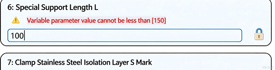
To prevent designers from creating supports that do not meet standard requirements, certain open parameters are restricted during support customization, such as maximum/minimum values and selectable options. Some restrictions come from standard requirements, while others require a secondary confirmation by the designer.
(1) Restrictions due to standard requirements: the standard imposes a minimum value on this type of pipe shoe length.
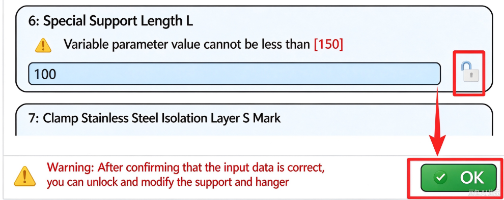
(2) Restrictions requiring secondary confirmation: the designer must confirm whether to change the pipe shoe material to stainless steel. ("Selected row invalid" means no matching default value was found, not that the selected value is invalid; this prompt will be improved in a future version.)

After confirmation, to modify the support beyond the restriction, click to unlock the "lock" and then click the OK button.
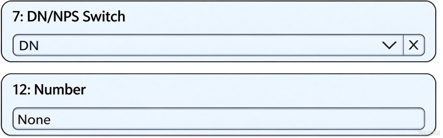
Non-consecutive Numbers
When modifying, you may notice that the parameter numbers are not consecutive. This is because some parameters do not require user setting and are hidden due to strong inter-relationships.
Snap
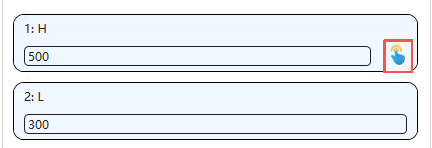
Parameters with a Snap button can interact with the model in the graphic interface to quickly obtain parameter values. For example, a T-support height can be quickly set by snapping to the supporting surface.
Snap operation: Click the Snap button, press and hold the left mouse button, and move close to the snap target (point, line, surface, etc.). Release the left mouse button when the cursor changes.
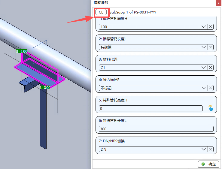
When you need to modify the variable parameters of another sub-support, first select that sub-support in the model, then click the CE button to switch. The information after the CE button shows the name of the current sub-support.
Sub-type Replacement
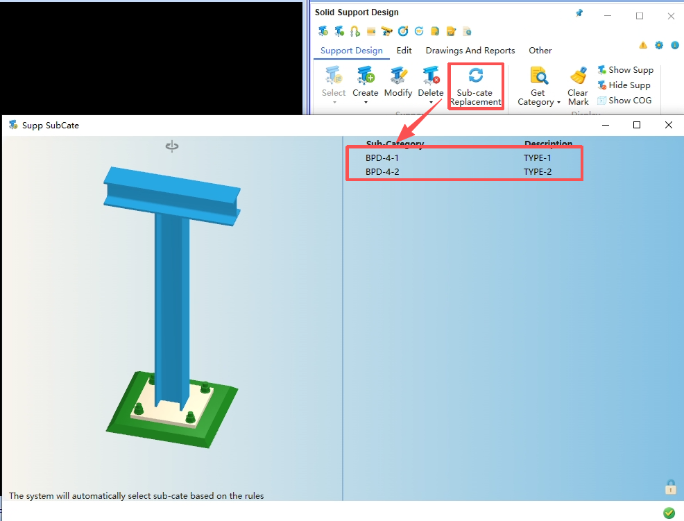
Sub-type replacement is for quickly changing the sub-type selection of a support. First select the sub-support in the graphic interface, then click the Sub-type Replacement button in the Function Menu area to open the support sub-type selection interface.
Delete
There are two basic deletion methods: deleting an entire support group, and deleting a specific sub-support. SolidSupport also provides a third deletion method — batch deletion (introduced in the Batch Management section).
Delete Support
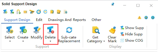
After selecting a support/hanger, click the Delete button in the Function Menu area. After confirmation, the entire support group and its corresponding attachment point will be deleted.
Delete Sub-support
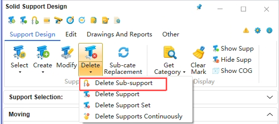
Select a sub-support within the support group (note: it cannot be the main support), click the dropdown arrow next to the Delete button in the Function Menu area, and choose Delete Sub-support (alternatively, click the Delete Sub-support button in the Sub-support Operations area). After confirmation, that sub-support will be deleted.
Batch Delete Supports
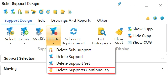
Click the dropdown arrow next to the Delete button in the Function Menu area and choose Batch Delete Supports. Then select multiple support groups one by one in the graphic interface, click on blank space to exit multi-selection mode, and after confirmation, the selected support groups will be batch-deleted.
Sub-support Operations
Sub-support operations are for fine-tuning the position and angle of sub-supports. This process shifts the position and angle of the sub-support relative to the attachment point, and is generally used for combined support scenarios. The Sub-support Operations area integrates all functions related to sub-support operations.
Move Sub-support
The purpose of moving a sub-support is to adjust the position of certain sub-supports within a support group. It changes the relative positions between sub-supports and is independent of the attachment point. Note that this function differs from Section 5.3 (Move): moving a sub-support does not change the attachment point position.
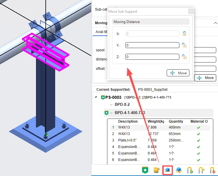
(1) Select the sub-support and click the Move Sub-support button in the Sub-support Operations area.

(2) In the dialog, enter the move distance for each direction, paying attention to the coordinate axes in the graphic interface. Note that the pipe axial direction (X direction) is locked by default; unlock it if necessary before entering the distance. Then click Move.
Rotate Sub-support
The purpose of rotating a sub-support is to adjust the orientation of certain sub-supports within a support group. It changes the relative orientation between sub-supports.
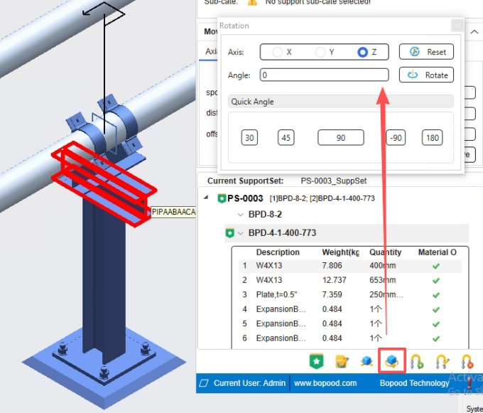
(1) Select the sub-support and click the Rotate Sub-support button in the Sub-support Operations area.

(2) In the dialog, select the rotation axis, enter the rotation angle, and click Rotate.
Get Selection
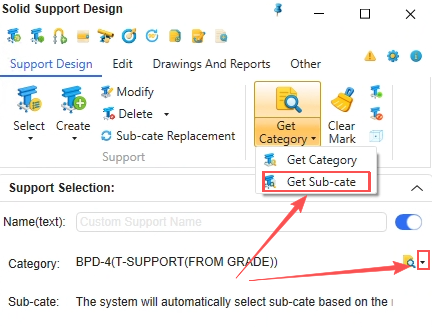
Get Selection is for quickly obtaining the support type of an existing support in the graphic interface; it is a simplified version of Select Type. There are two modes: Get Type and Get Sub-type.
Get Type
(1) Select a sub-support in the graphic interface and click the Get Selection button in the Function Menu area (alternatively, click the Get Selection button in the Selection Info area).
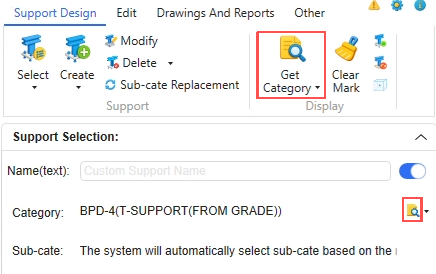
(2) After entering the sub-type selection interface, select a sub-type and click OK.
Get Sub-type
Select a sub-support in the graphic interface, click the dropdown arrow of Get Selection in the Function Menu area, and choose Get Sub-type (alternatively, click the dropdown arrow of Get Selection in the Selection Info area and choose Get Sub-type). This directly obtains the sub-type of the current support without entering the sub-type selection interface.
Show/Hide Supports
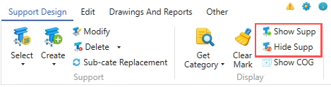
Select BRAN, PIPE, ZONE, SITE, or other levels in the catalog tree, then click the Show/Hide Supports button in the Function Menu area to show or hide support entities in the graphic interface.
Show Center of Gravity
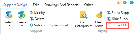
Select a sub-support in the graphic interface, then click the Show Center of Gravity button in the Function Menu area to display the center of gravity position of the support entity.
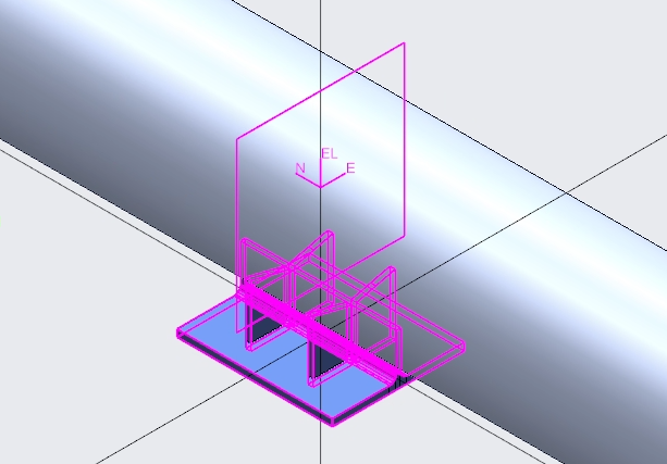
Clear Marks
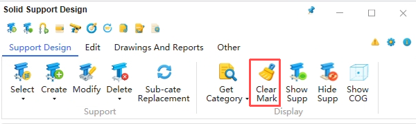
Click the Clear Marks button in the Function Menu area to clear marks in the graphic interface, such as the center-of-gravity mark from Section 4.10 and the position marks shown after axial move.
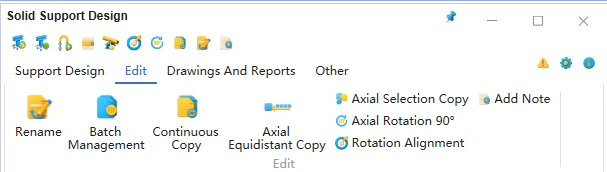
Support/Hanger Editing
Click the Edit button in the Function Menu area to switch to the support/hanger editing interface. The editing interface is mainly for further improving support design efficiency and completing support information.
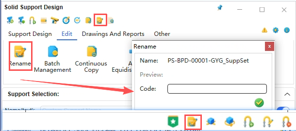
Rename
Click the Rename button in the Function Menu area (or the Rename button in the Sub-support Operations area) to rename the selected support. This operation modifies both the support group name and the attachment point name simultaneously. To maintain consistency between attachment point and support entity names, please use SolidSupport's built-in rename function.
Batch Management
Batch Management allows quick processing of all supports under the selected pipe directory, such as batch deletion, batch renaming, report export, and support model refresh.
Load Supports
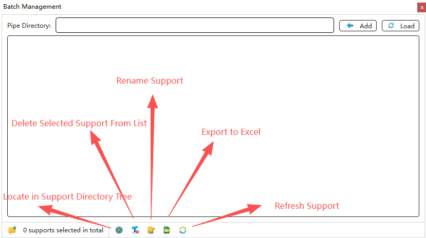
Click the Batch Management button in the Function Menu area to open the batch management interface.
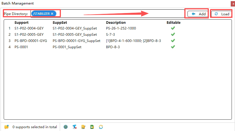
Add root directory to load: Select the root directory where the pipe resides in the catalog tree (can be a branch, pipe, node group, node set, or root node), click the Add Root Directory button, then click the Load Supports button to load support information.
Locate Support
Locate to attachment point: Select a support in the list, then click Locate to Attachment Point to find its position in the catalog tree.
Delete Support
Select supports in the list (multi-select allowed), then click the Delete Support button to delete the selected supports.
Rename Support
Select supports in the list (multi-select allowed), then click the Rename Support button to rename the selected supports.
Note: The renaming rules follow the naming rule settings in the configuration. When batch renaming, avoid using old naming rules, otherwise renaming may fail!
Export to Excel
Select supports in the list (multi-select allowed), then click the Export to Excel button to export the selected support information to Excel for viewing.
Refresh Support Model
Select supports in the list (multi-select allowed), then click the Refresh Support Model button to update the model data of the selected supports.
Usage
(1) Select a support group, click the Continuous Copy button in the Function Menu area (or the Continuous Copy button in the Quick Access area) to enter continuous copy mode.
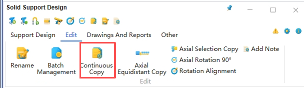
You can right-click or press the ESC key to exit continuous copy mode.
(3) Click continuously on pipes or fittings to generate supports. Note that copying is only possible on pipes of the same diameter.
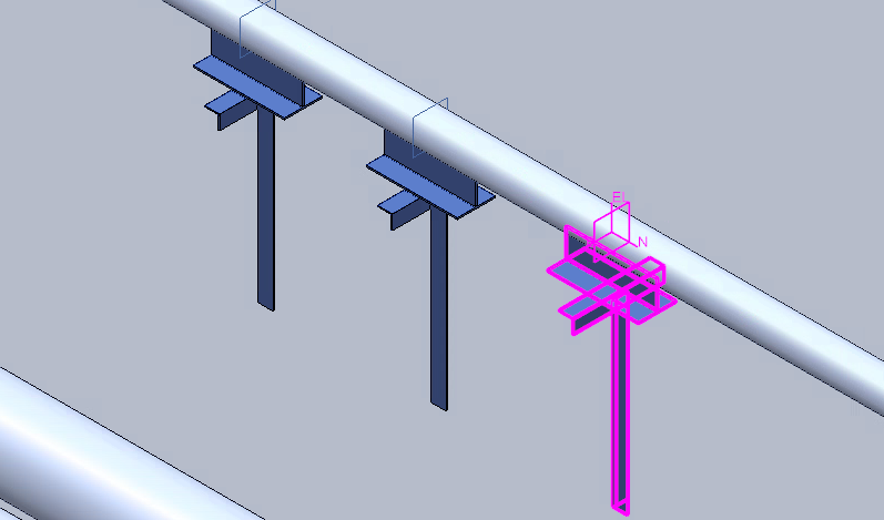
Difference from Continuous Quick Create
(1) Different operation targets: Continuous Copy operates on support groups; Continuous Quick Create operates on sub-supports.
(2) Different usage restrictions: Continuous Copy can only copy on pipes of the same diameter; Continuous Quick Create can be used on pipes of different diameters.
(3) Different generation results: Support groups from Continuous Copy are generated entirely from the data of the copied group; sub-supports from Continuous Quick Create are generated with default data.
Usage
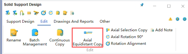
(1) Select a support group and click the Axial Equal-Spacing Copy button in the Function Menu area to open the corresponding interface.
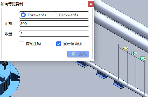
(2) Select the copy direction, enter the copy count and spacing. The graphic interface will mark the generated positions. You can choose whether to copy annotations along with the supports.
Notes
(1) Copying can only be performed on a straight pipe run of the same diameter and cannot exceed the length of that straight run.
(2) Crossing fittings automatically adjusts the order of attachment points in the catalog tree; no manual adjustment is needed. Note that reducers cannot be crossed.
(3) Suitable for support groups on pipe racks; allows quick copying of large numbers of identical support groups.
Axial Point-Selected Copy
Usage
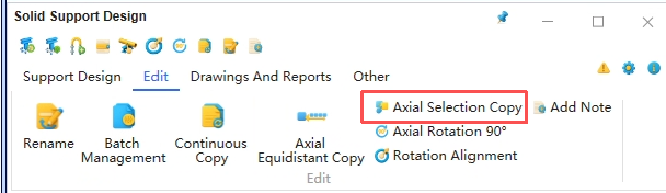
(1) Select a support group and click the Axial Equal-Spacing Copy button in the Function Menu area to open the corresponding interface.
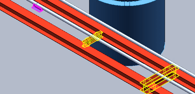
(2) The selected steel section will be highlighted. Finally, right-click or press the ESC key to exit axial point-selected copy mode.
Notes
(1) Includes the notes from Section 5.4.2.
(2) Suitable for copying supports on beams with unequal spacing; use Section 5.4 Axial Equal-Spacing Copy for equal spacing.
(3) Generates at the center point of the reference steel section, eliminating the support positioning step.
Usage
Select a support group and click the Axial Rotate 90° button in the Function Menu area (or the Axial Rotate 90° button in the Quick Access area) to quickly rotate the support group 90° around the pipe centerline.
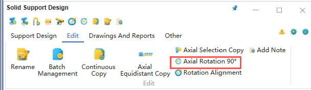
Difference from Rotate Sub-support
Different operation targets: Axial Rotate 90° operates on support groups; Rotate Sub-support operates on sub-supports.
Usage
Select a support group and click the Rotate to Align button in the Function Menu area (or the Rotate to Align button in the Quick Access area) to quickly align the support group around the pipe centerline to the center of a target object. This is commonly used for pipe supports attached to towers.
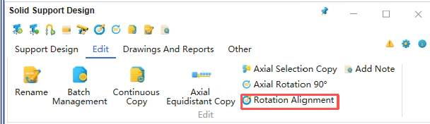
Add Annotation
Add Annotation creates an annotation attachment point under the attachment point corresponding to the current support group, used to annotate the support at that position. The annotation information is also written into the support group's description attribute. After adding, the annotation can be viewed by previewing the ISO drawing, and the annotation content can also be extracted when generating the support schedule.
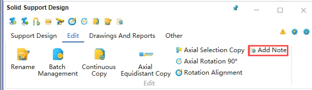
Add Annotation
(1) Select a support group and click the Add Annotation button in the Function Menu area to open the annotation interface. Enter the annotation text in the text box and click Add to generate an annotation attachment point.
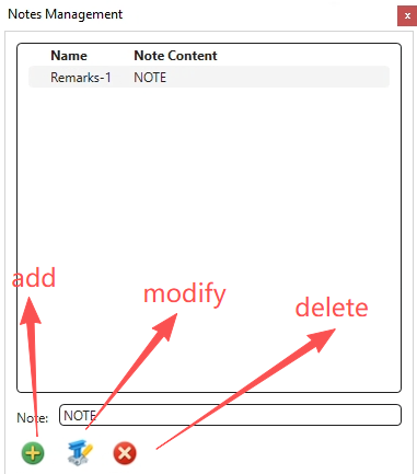
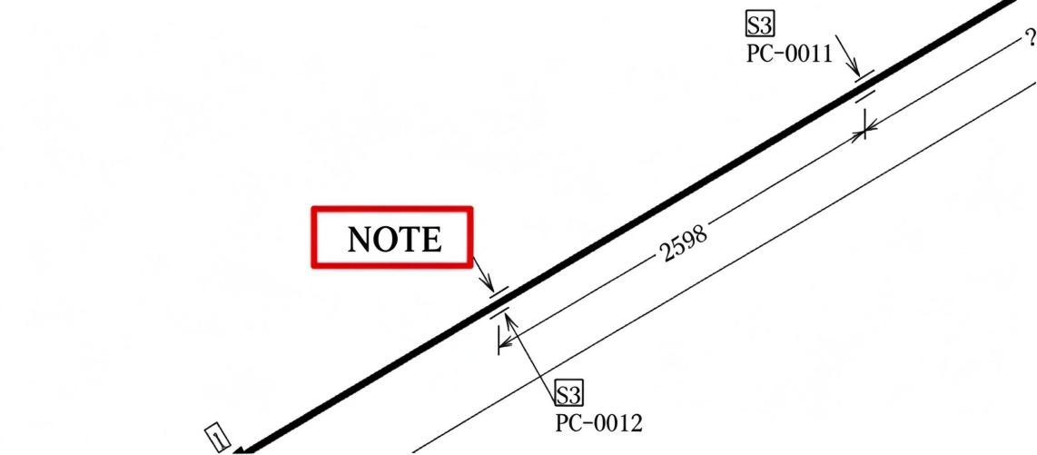
(2) View the support annotation information on the ISO drawing.
(3) Check the support attributes to verify that the annotation content has been written to the description attribute.
Support/Hanger Reports
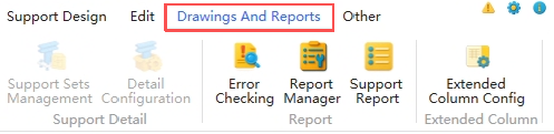
Click the Drawings & Reports button in the Function Menu area to switch interfaces. Drawings & Reports is mainly used to generate support design deliverables, such as material takeoff and support schedules. Before performing these operations, please run Error Check first to ensure that the data in attachment points and support entities is correct.
Error Check
To ensure the accuracy of deliverable data, please always run Error Check before using Material Takeoff, Support Schedule, or batch operations, to verify that the data in attachment points and support entities is correct.
Error Check
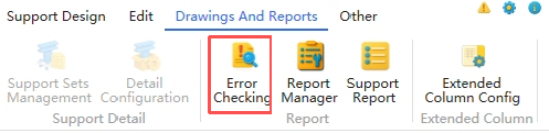
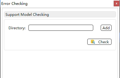
(1) Click the Error Check button in the Function Menu area to open the error check dialog.
(2) In the dialog, specify the check directory for supports and click Check.
- Check directory: the branch / pipe / node group / node set / root node where the support resides.
Error Handling
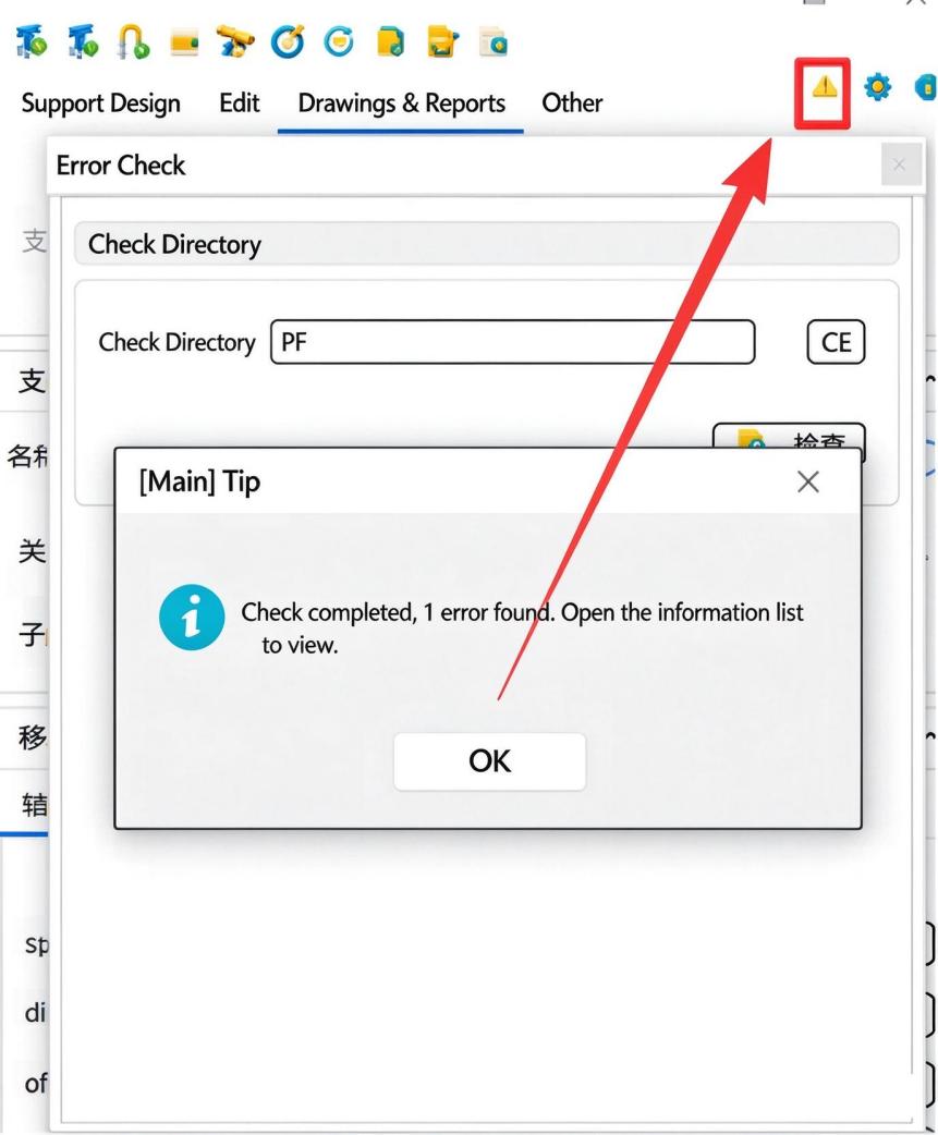
(1) If errors are found, the Error Messages button in the Function Menu area will flash. Click the Error Messages button to view the error list.
(2) In the error list, select the row with the error, right-click and choose Locate to find the position in the catalog tree. After resolving the error according to the instructions, you can ignore it.
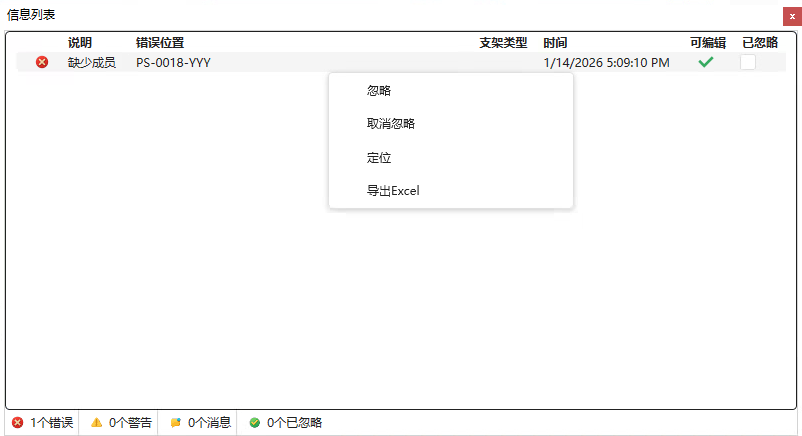
(3) Note that the same object may generate multiple errors. After deleting the object, the errors in the list do not disappear automatically and must be manually ignored.
Support/Hanger Reports
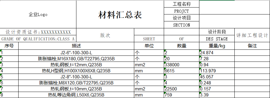
- The support/hanger report function can generate both a support schedule and a material takeoff table.
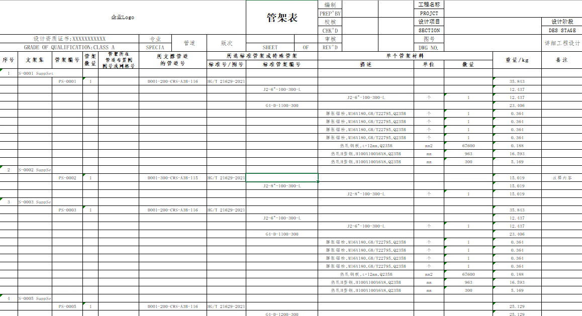
- The support schedule focuses on displaying individual support information. From the report, users can see detailed information for each support, such as: serial number, pipeline number, component description and quantity, etc.
Support material statistics are available in two modes: loose items and complete assemblies. All supports are counted as loose items by default; supports to be counted as complete assemblies must be configured by the user. See Section 7.2.3 for details.
- The operation steps are as follows:
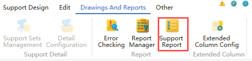
(1) Click the Support Report button.
- Load supports.
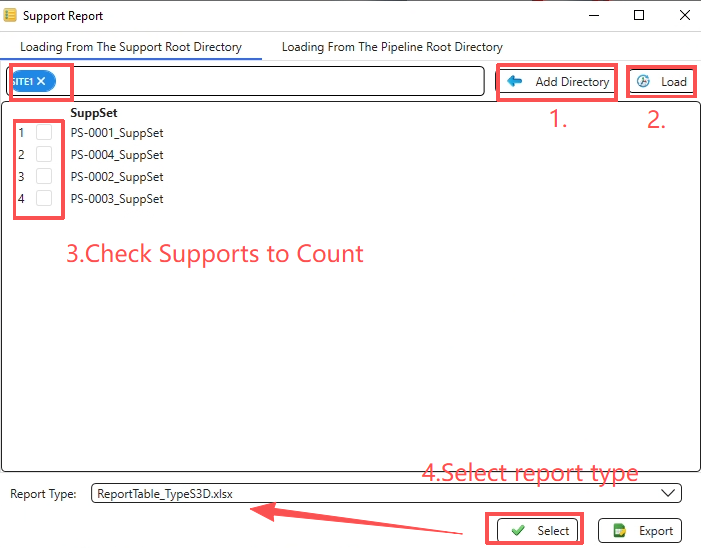
- Select the node group containing the support models in the catalog tree, click Add Root Directory (multiple directories can be added at once). After loading supports, the order shown in the table is the order in the final report; click any table header to sort that column. Finally, batch-select and check the supports to be included in the statistics.
- ②Load multiple pipelines by pipeline number
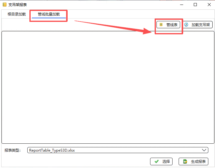
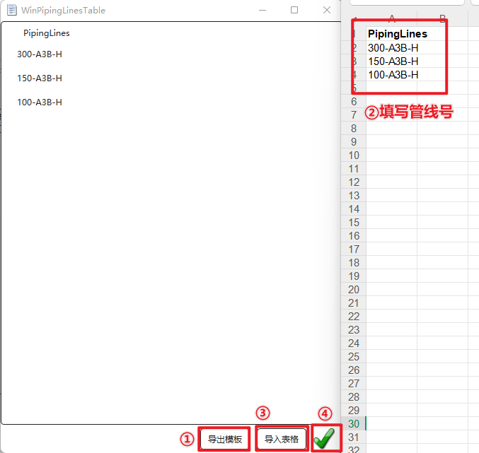
- Import an Excel file to load supports from multiple pipelines.
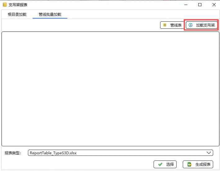
- Finally,load the supports as in method ①.
(3) Select report type
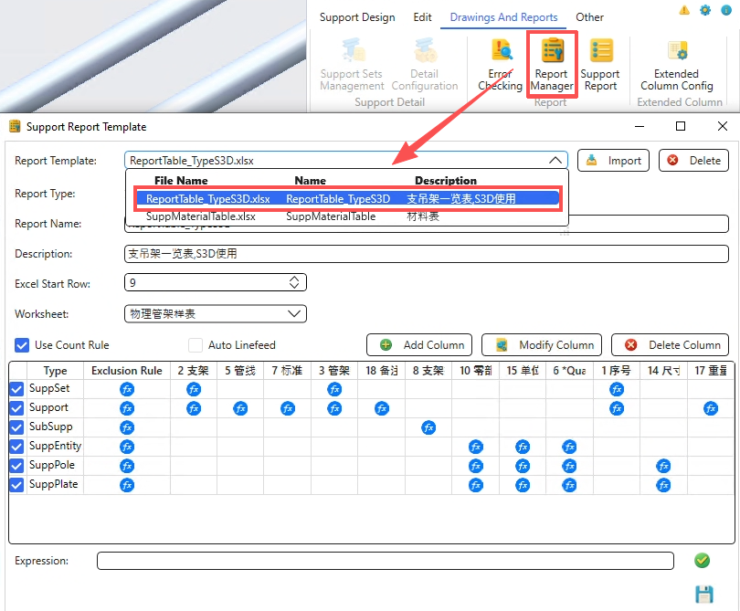
- There are 2 default configurations: 1 support schedule template and 1 material takeoff template. Select the report template as needed.

(4) Generate report
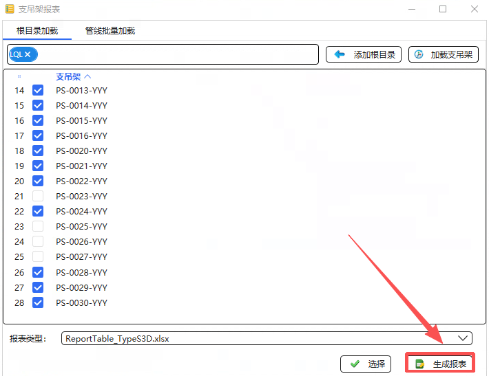
- The schedule template output is as follows:
- The material table template output is as follows:
Report Management
- In Report Management, users can view detailed information for all configurations and modify them to make the exported reports meet company or project requirements. For unified management, this is generally handled by the database administrator. Below, we select a report configuration from the configuration file path and make a copy to demonstrate how to modify a configuration.
- Report template configuration files are located in the SolidSupport 2.2 plugin installation directory (a folder named SolidSupport2.2_S3D). The reference path is as follows:

Report Configuration File
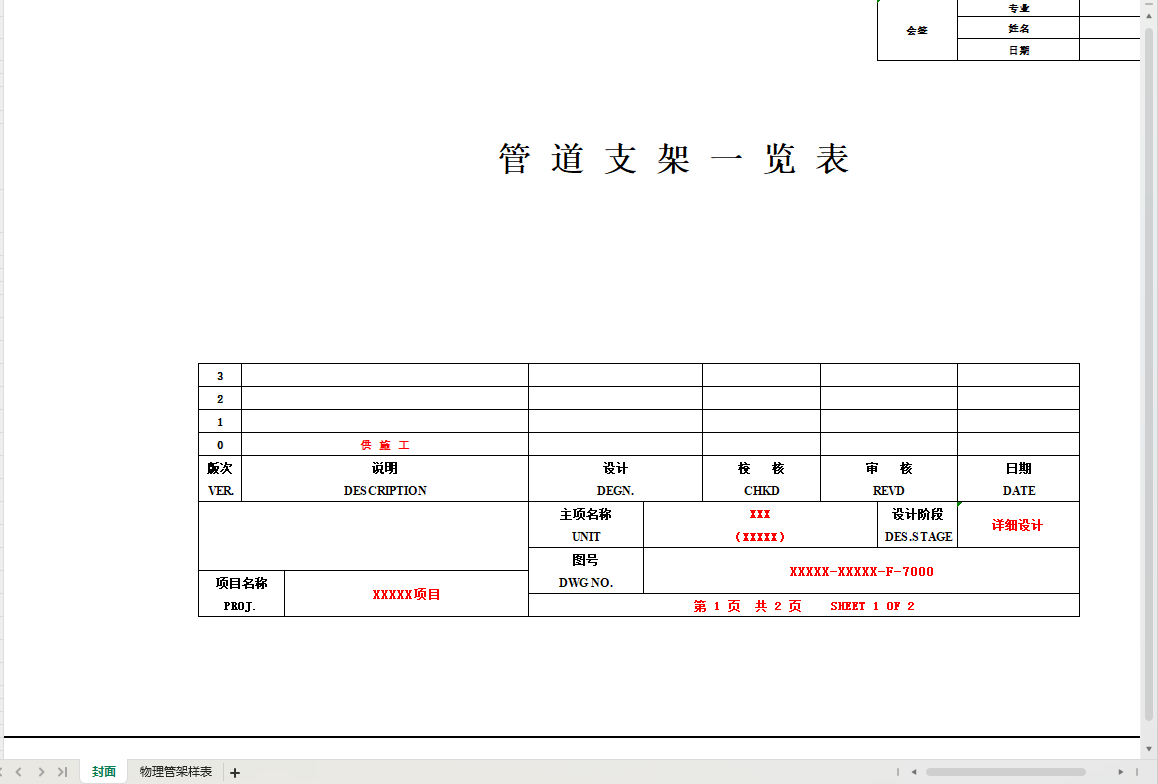
- Report configuration files are in Excel format (.xlsx). When opened, the file contains 2 sheets: a cover sheet and a physical support sample sheet.
(1) Cover sheet
- The content and format of the cover sheet can be modified by the user as needed; the software does not modify its data.
(2) Physical support sample sheet
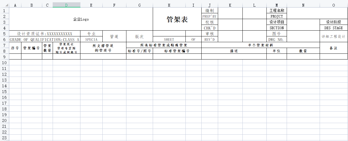
- The physical support sample sheet is where support data is exported. Users can also customize the content and format of the table; after modification, the output information can be configured in the software according to this format.
Custom Report Configuration
(1) Modify the cover sheet and physical support sample sheet as needed, then save and close.
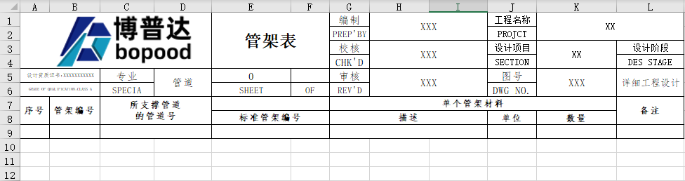
(2) In the support software, click Report Management to enter simple report configuration, and select the modified configuration file.
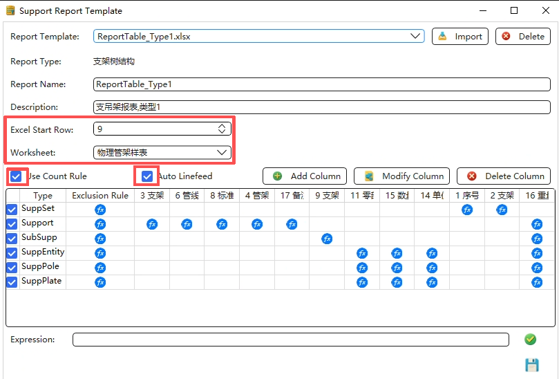
- In the report basic information, fill in the report name and description;
- The starting row indicates which row in the Excel configuration file the output information begins at; this must be determined based on the actual table format. The worksheet refers to the physical support sample sheet where information is exported.
- The project complete-assembly rule refers to supports whose statistics mode has been set to complete assembly in the support type configuration.
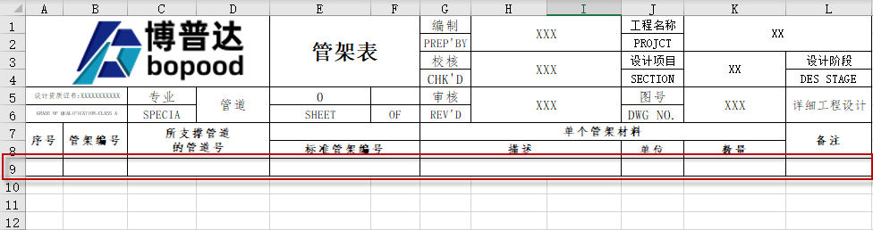
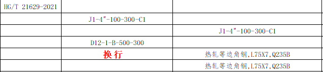
- If you want sub-supports and components to wrap to new lines in the report, check 'Auto-wrap child nodes'.

(3) Support Set Information
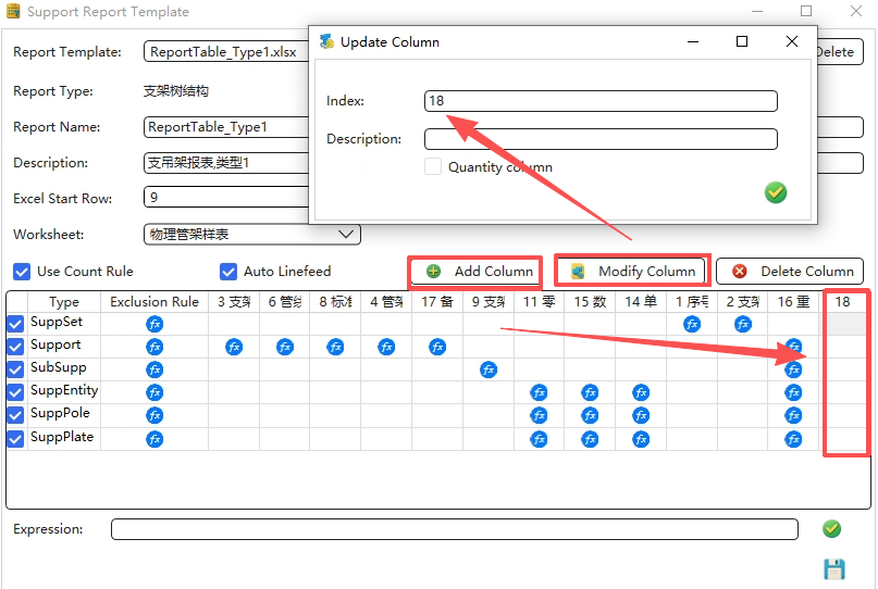
- Control the support information columns in the report by adding or deleting columns. The column number corresponds to the Excel column number and adjusts which column each piece of support information appears in the exported report. The description is the explanation or name of each column in the software and does not appear in the report. If a column needs to be aggregated, check 'Mark as quantity summary column' (e.g., quantity). The 'Attribute Expression' is the actual information output to the report; it can be a fixed value or an expression.
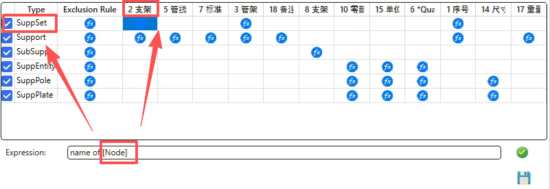
- In the expression, [suppset] refers to the content in the 'Type' column of the current row. For example, [suppset] entered at the support set level refers to SuppSet, i.e., the model type :SST_SuppSet. After filling in the attribute expression and corresponding output column according to the format in the configuration file, click Save at the bottom-right.
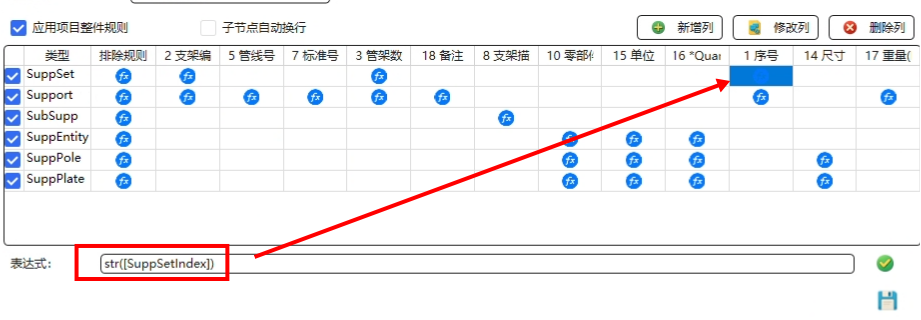
- Note: The index here is the support set index: str([suppsetIndex]). To annotate the support index, click the corresponding blank field, enter the expression str([suppIndex]), then modify and save. Similarly, to annotate the sub-support index, the expression should be str([subsuppIndex]); to annotate the component index, the expression should be str([compIndex]).
(4) Support Information
- In the expression, [Node] refers to the content in the 'Type' column of the current row. For example, [Node] entered in the support number field refers to Support, i.e., the model type :SST_Support. After filling in the attribute expression and corresponding output column according to the format in the configuration file, click Save at the bottom-right.
(5) Sub-support Information
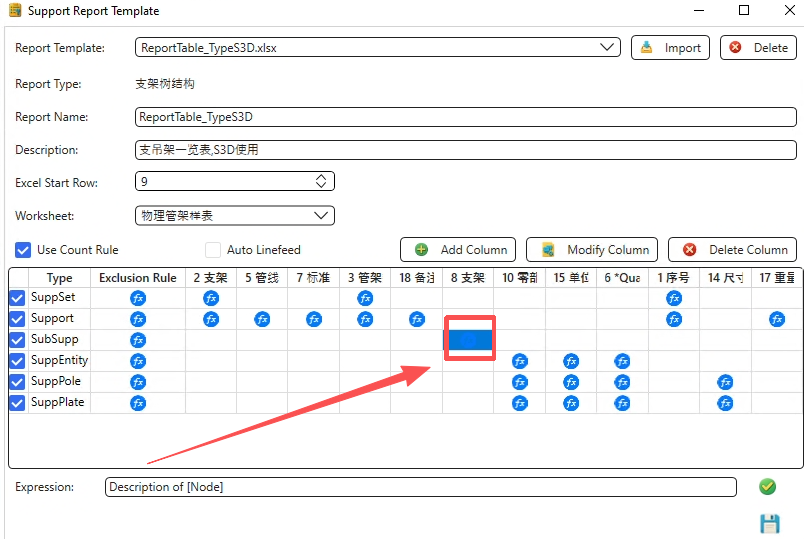
- In the SubSupp row, [Node] refers to the sub-support SubSupp, corresponding to model type :SST_SubSupport. The support code is usually stored in its description attribute, so the attribute expression should be Description of [Node].
(6) Component Information
- Similarly, [Node] can refer to the three component types under the component set :SST_CompSet: SuppEntity, SuppPole, and SuppPlate, corresponding to model types :SST_Entity, :SST_Pole, and :SST_Plate respectively.
- Component attribute expressions must be defined separately for each component type. The component description uses a fixed format and the expression does not need to be changed; only the Excel column number needs to be modified. The unit is related to the quantity: by default, the unit for complete assemblies (Entity) is 'pcs', for bars (Pole) it is mm, and for plates (Plate) it is mm². The quantity values for bars and plates are at the mm level; to switch to the m level, both the unit and quantity must be changed together, as shown below.
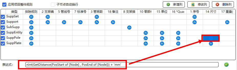
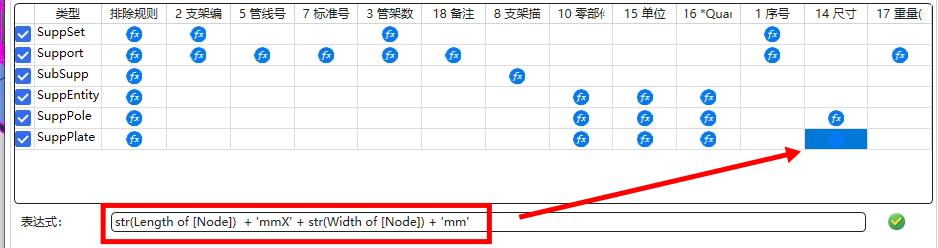
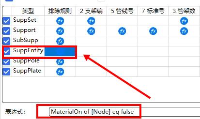
- The exclusion rule indicates that certain items should not appear in the report. The default is generally sufficient: False at the support and sub-support levels, and MaterialOn of [Node] eq false at the component level.
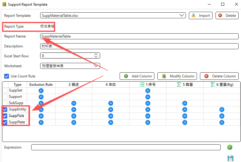
- Note: This report template is of the support tree structure type, and the support level cannot be removed. If you need to output only component materials in a support report, use the standard table type; see the report template SuppMaterialTable.
Support Type Configuration
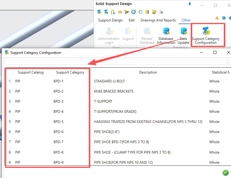
- In the support type configuration interface, users can see the total number of support types in the current database, the material statistics mode for each type, and whether each type is visible in the selection interface.
- Set Statistics Mode
- For ease of procurement and installation, some special supports may be better output as complete assemblies (a complete assembly means counting the support by its code), such as Class C spring supports/hangers.
- When C1 is counted as loose items, the component list becomes complex and procurement is more difficult. In this case, select the support type to change, right-click and choose Complete Assembly Statistics Mode, then click OK at the bottom-right.
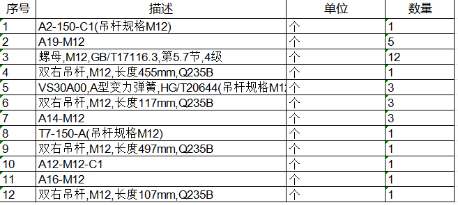
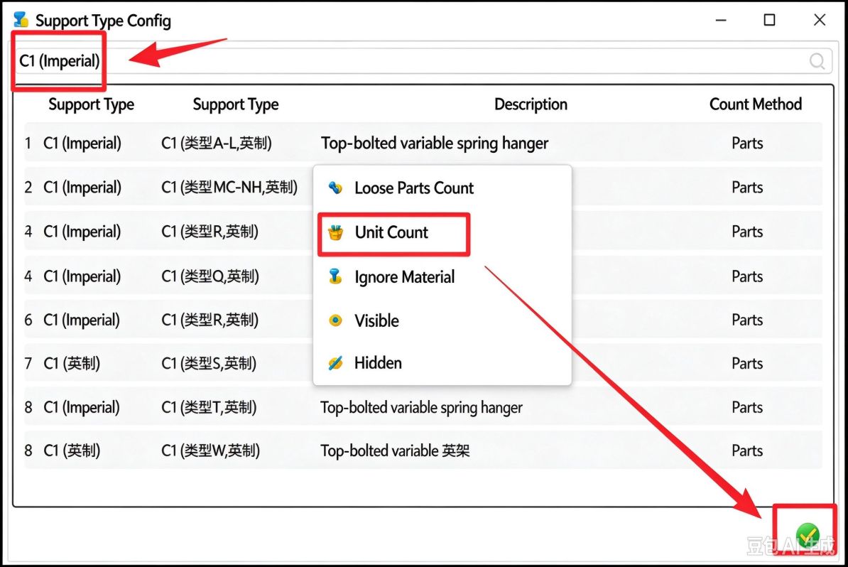
- When we run the material statistics again, we will see that these supports are now counted as complete assemblies.

- Furthermore, if there is a special need to exclude the material output for a certain support type, we can set it to 'Ignore' to disable its material statistics.
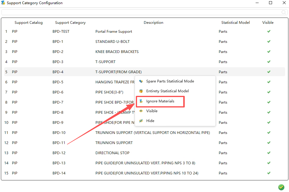
- Set Support Type Visibility
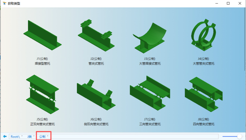
- For the HG/T 21629-2021 support standard, pipe outside diameters are divided into Series I and Series II. Support types using Series I are marked (Imperial), those using Series II are marked (Metric), and support types independent of pipe outside diameter have no mark, such as D2 and D3.
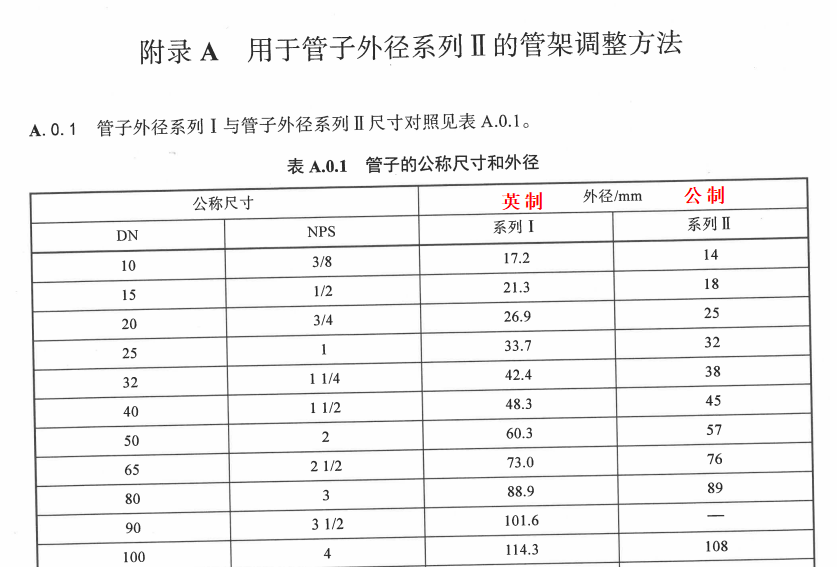
- By default, both Imperial and Metric supports are displayed simultaneously in the support selection interface, which may cause designers to select the wrong support type. Therefore, before adding supports, log in with the administrator account and hide the unneeded support types to prevent errors.
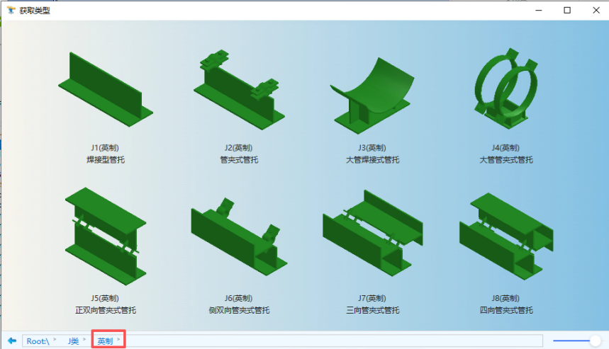
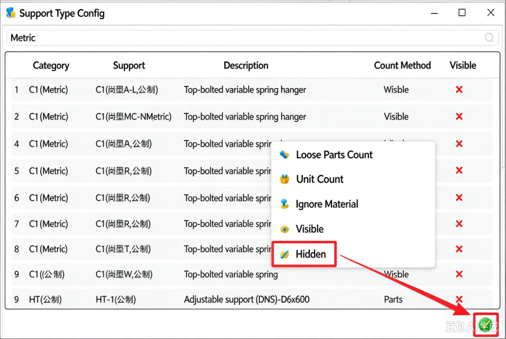
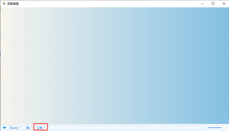
- Similarly, in the support type configuration, select the support types to hide, right-click and choose Hide, then click Confirm at the bottom-right. After logging out of the administrator account, the hidden support types will no longer appear in the selection interface.
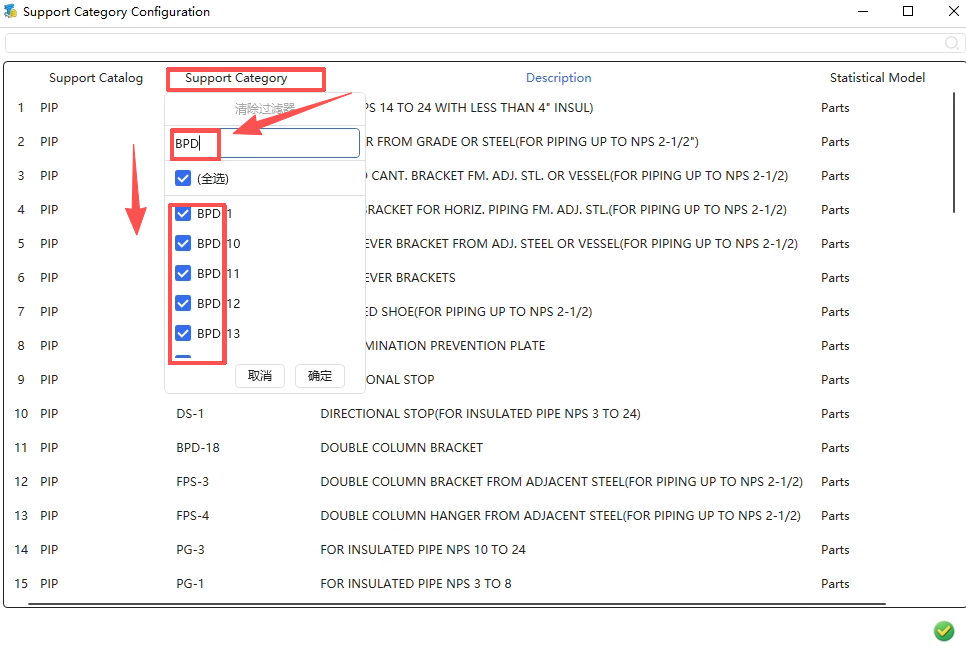
- Filter Function
- The filter function helps us quickly and accurately find the desired support types, facilitating batch setting of statistics mode and visibility.
- The first is the keyword search box mentioned earlier.
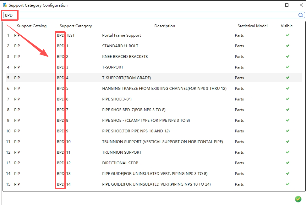
- The second is to open the filter on the right side of the header row and enter a search term to filter. For example, to hide all Metric support types, press Ctrl+A to select all filter results, then right-click and set to Hide. Left-click a header to sort by that column.
Automatic Support Naming
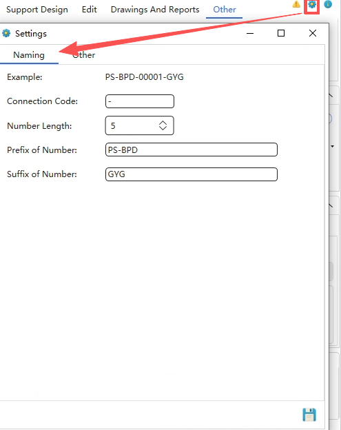
(1) Automatic support naming
- Users can customize the support naming rules, setting the separator, serial number digits, number prefix, and number suffix.
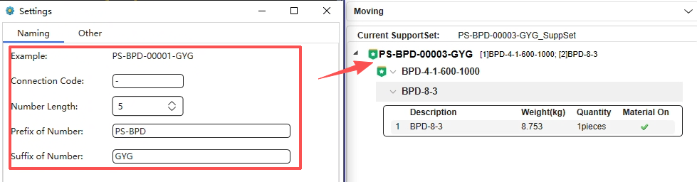
- Note: This setting does not apply to existing supports; it only affects newly created supports. Therefore, set it up before adding supports. If changes are needed midway, batch-rename the affected supports once to refresh the data so the new naming rules apply to existing supports as well.
Other Settings
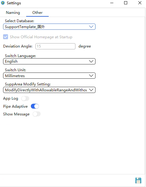
- Select Database
- Users can switch the support database here (if multiple databases are available);
- Show Official Homepage on Startup
- Users can choose whether to show the official homepage on startup here;
- Pipe Judgment Deviation Angle
- Because different support types are suited to different scenarios — some can only be created on vertical pipes, others only on horizontal pipes — a pipe judgment deviation angle must be set to accommodate pipes with slight deviations.
- Language Selection
- The support design interface language can be switched from Simplified Chinese to English.
- Unit Selection
- Set according to the units of the design software.
- Zone Modification Settings
- The zone range settings when a support set is configured as a shared support.
- Program Log
- When enabled, records certain key operations to help technical staff trace error information.
- Pipe Adaptation
- When the pipe diameter or insulation thickness is modified, the support's bore or insulation-identified height will automatically adjust.
Read This First for Administrators
- Before starting to add supports in a project, the project administrator must perform some basic settings on the support software (on the designers' computers) to reduce errors.
(1) Select the appropriate support database;
(2) Hide unneeded support types to prevent designers from using the wrong supports (e.g., in HG/T 21629-2021, supports have Imperial and Metric variants corresponding to Series I and Series II pipe outside diameters; hide the Imperial/Metric supports as appropriate to prevent misuse);
(3) If using Imperial (HG/T 21629-2021) supports, determine how the pipe diameter is represented in the support code — e.g., J2-3"-100-300-C1 uses inches, while J2-80-100-300-C1 uses DN.
(4) Set the material statistics mode for each support type (loose items / complete assembly / ignore; spring supports/hangers and rigid hangers are recommended as complete assembly);
(5) Define the support naming rules for each piping designer to avoid duplicate names when syncing data;
(6) Plan the storage location of support entities.
Error Log
- During software use, you may encounter error issues not covered by this tutorial. In such cases, enable the error log switch to record the error messages. The log enable switch is located as shown below.
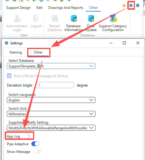
- After enabling the program log, reproduce the operation that caused the error to record it. The log files are located at Documents\bopood\SolidSupport_v2.0\Logs.
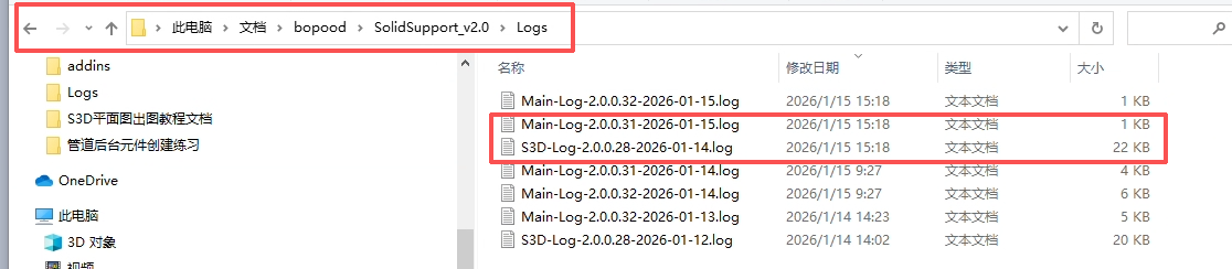
- Send us the two most recently timestamped log files, Main and S3D, and Bopood staff will immediately begin resolving the issue.
