1.3 SolidSupport后台管理教程英文版

SolidSupport Hanger Database Management Module
SolidSupport Hanger Database Management Module
SolidSupport is a 3D solid hanger program for PDMS and E3D, developed by Chengdu Bopuda Technology Co., Ltd. It integrates the Hanger Engine developed in-house by Bopuda Technology and takes an innovative parametric-driven approach to creating hanger databases. With the powerful administration system, users can customize any type of hanger. SolidSupport offers fast customization, a high degree of freedom, an easy learning curve, complete material information, and a high level of intelligence.
SolidSupport has two main modules: hanger design and hanger database management. The hanger database management module is for hanger customization personnel, who design hanger types in it and assemble them in a parametric-driven way.
This document is the tutorial for the hanger database management module and is demonstrated on AVEVA's PDMS12.1 3D design platform. It applies to the SolidSupport_V1.5.1 series. For questions, request technical support through the Chengdu Bopuda Technology Co., Ltd. website (www.bopood.com).
Preparation consists of creating a new project to serve as the database for hanger customization. This part requires the skills to create and configure a project in PDMS. All later content builds on this project: creating hanger parts and designing hanger types through the hanger database management module.
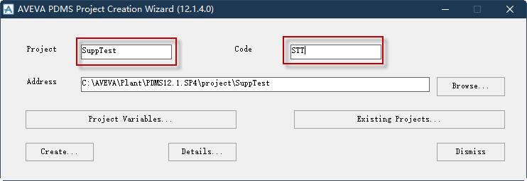
(1) Find the ProjectCreation.bat batch file in the PDMS installation root directory and double-click it to start. Enter the Project and Code information in the window that appears and click Create… to create a new project. This project stores the basic parts, special properties, and hanger data.
(2) Create a new project as shown below:
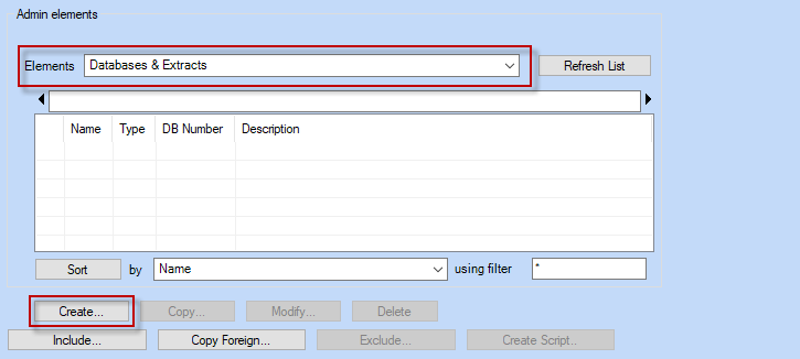
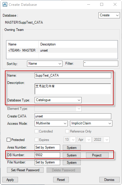
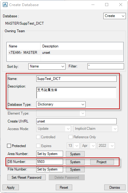
(1) Enter the Admin module of the SuppTest project and select Databases&Extracts in Elements. Click Create…, select MasterDB in the dialog box and click OK. Create the hanger test DB, component library DB, and attribute DB in turn.
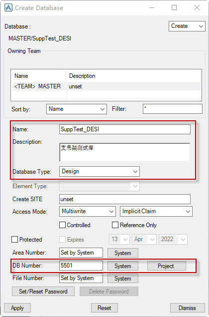
(2) Create the hanger test DB, component library, and attribute library in turn as shown below. Note the different DatabaseType of each DB.
(1) The SolidSupport basic attribute library is built by Chengdu Bopuda Technology specifically for hanger databases and contains hanger ATTAs, common hanger properties, and more. It consists mainly of three databases: the SDS component library (/SDS_V1.5_CATA), the SDS attribute library (/SDS_V1.5_DICT), and the SDS drawing library (/SDS_V1.5_PADD).
(2) Bopuda Technology currently provides two identical SolidSupport basic attribute libraries, SolidSupport_V1.5_NO1 and SolidSupport_V1.5_NO2. They differ only in DB Number, which avoids clashing with DB Numbers already used by the company. SolidSupport_V1.5_NO1 uses DB Numbers 6661-6662-6663; SolidSupport_V1.5_NO2 uses 4451-4452-4453.
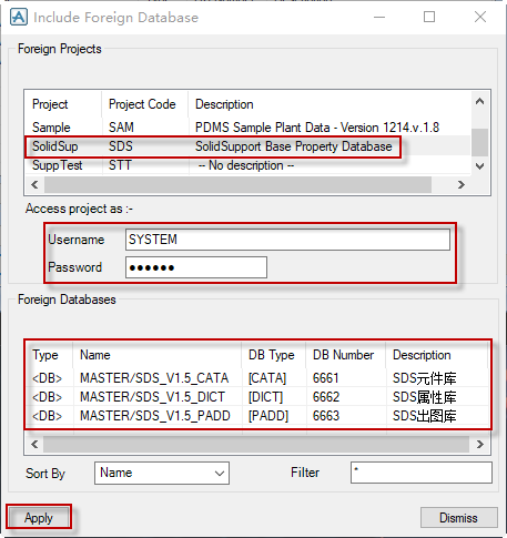
(3) Once the SolidSupport_V1.5_NO1 project is readable by configuring the project and the PDMS evars file, enter the Admin module of SuppTest and select Databases&Extracts in Elements. Click Include…, find the project with ProjectCode SDS in the dialog box, and include its three DBs in the DBs of the SuppTest project. Username is SYSTEM and password is XXXXXX, as shown below:
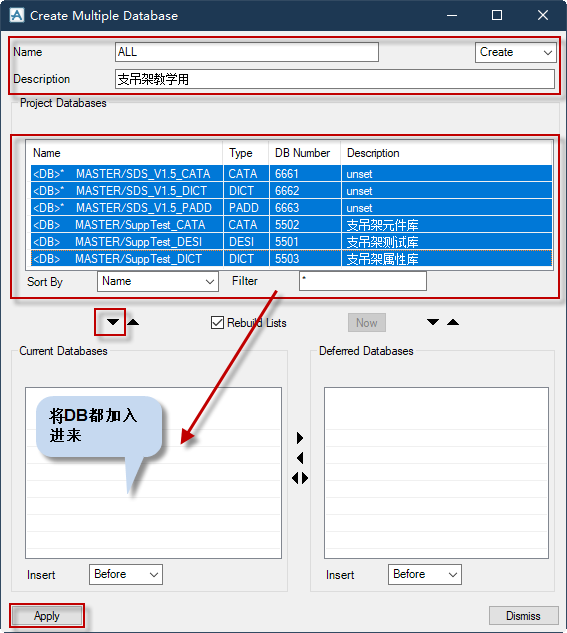
(1) Select MDBs in Elements. Click Create…, complete the MDB Name and Description in the dialog box, and add the DBs under ProjectDatabases to CurrentDatabases.
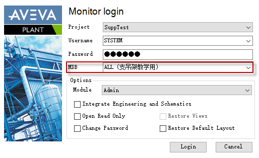
(1) After completing the steps above, save and exit the SuppTest project, then log in to the Admin module again, selecting the MDB on the project login screen, as shown below:
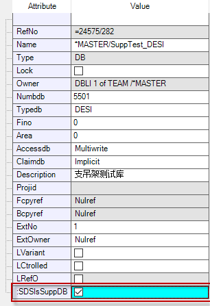
(2) Set the :SDSIsSuppDB property of the hanger test DB to TRUE, as shown below:
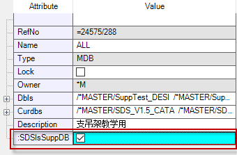
(3) Set the :SDSIsSuppDB property of the MDB to TRUE, as shown below:
Once the project is created, the databases configured, and the properties set as described above, you can customize supports in the hanger database management module. Specifically, log in to the Design module of the SuppTest project, click BopoodTech in the PDMS menu bar, and choose Hanger Database Management under SolidSupport.
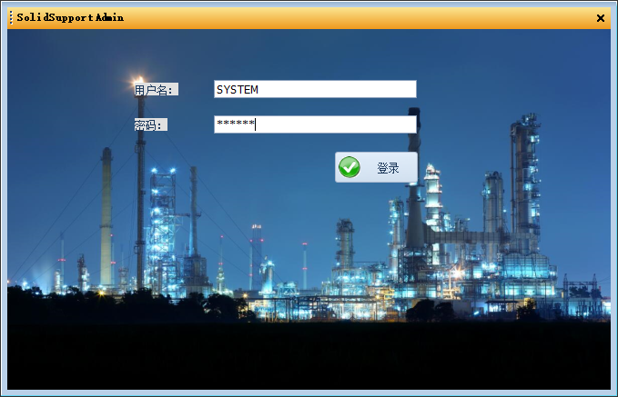
Enter SYSTEM as the user name and XXXXXX as the password in the dialog box, then click Log In to enter the hanger database management module. If a database upgrade prompt appears, click OK as prompted.
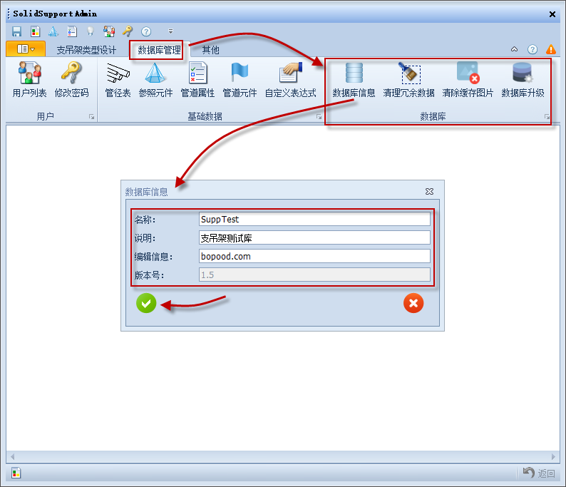
In the hanger database management module, click Database Management in the menu bar and left-click Database Information on the database toolbar. Complete the database information in the dialog box.
The UI consists of three parts: hanger type design, database management, and other.
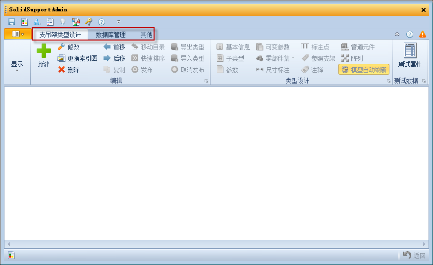
Hanger type design consists of four parts: display, editing, type design, and test data. Most hanger customization work is done here.
Database management consists of three parts: users, basic data, and database. The basic parts, pipe diameter tables, pipe properties, and pipe components used in hanger customization are configured here.
Other contains the UI theme and About, where you can switch theme skins and view software version information.
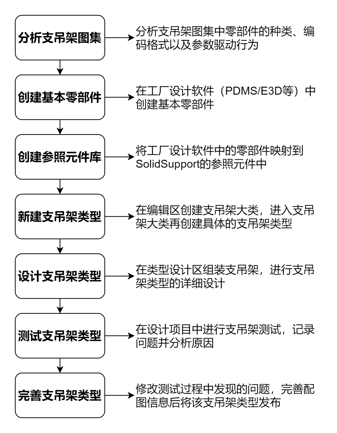
The hanger design workflow has seven steps: analyze the hanger drawing set, create basic parts, create the reference component library, create a hanger type, design the hanger type, test the hanger type, and refine the hanger type.
(1) For a given hanger drawing set, first gain an overall understanding of it: part composition, part specifications and material requirements, coding requirements, and parametric behavior (how the hanger shape changes, how many parameters control the coding result, and how they control it).
(2) The following uses D12 (T-shaped/inverted T-shaped support) in HG/T21629-2021 as an example of drawing analysis.
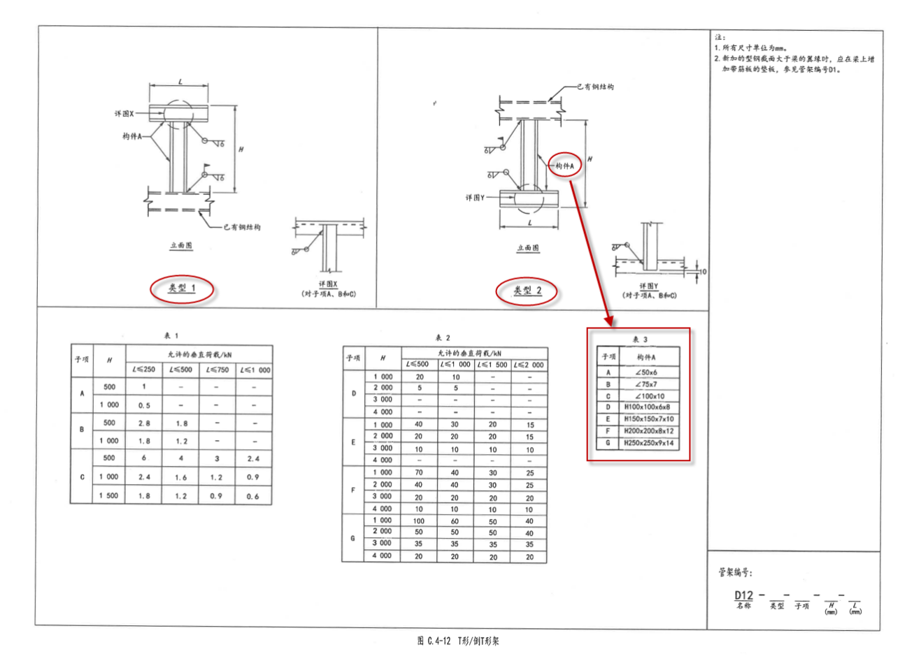
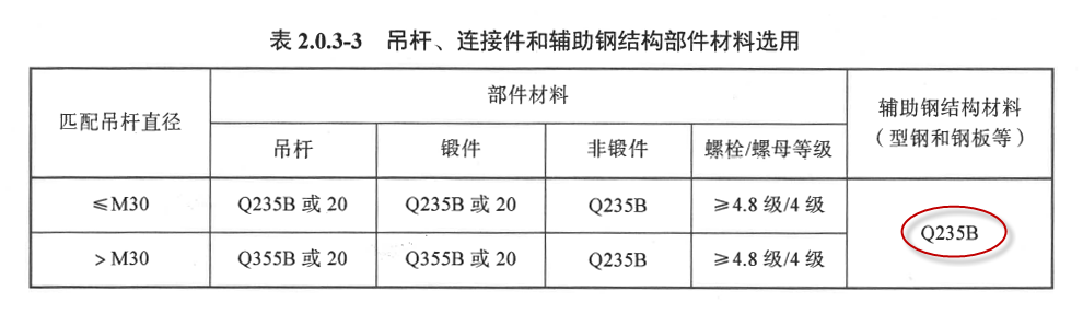
For type 1, the structural steel section of member A divides it into 7 sub-items, so this hanger needs 7 structural steel parts of different specifications. The dimensions show that dimension L and dimension H control its shape. The drawing set sets no special requirement for the steel material, so according to Table 2.0.3-3 of the standard (material selection for rods, connectors, and auxiliary steel structure parts), the auxiliary steel structure material is Q235B.
All parts used to assemble a hanger come from the reference component library. Before building that library, create the corresponding part library in the relevant plant design software (such as PDMS12.0, PDMS12.1 and E3D2.1) and map its specification reference (SPCO) to the reference components in the hanger database management module.
(1) Design hanger parts in the Paragon module of the SuppTest project as needed. This is PDMS parametric model design, which you should learn from other tutorials; this document does not cover it due to space limits.
(2) When designing a part, if its shape is variable, define variable parameters and apply them in the model design. After defining variable parameters in Paragon, you can control the part's shape changes through the hanger database management module.
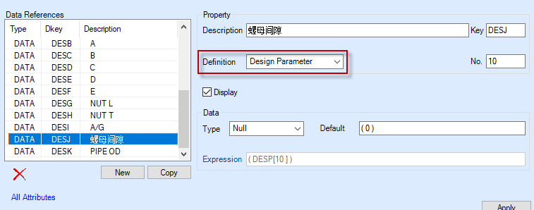
(3) After finishing the part design, set up its specification table. Create the specification table with a command; you only need to set the component reference (Catref) and description reference (Detref). An example specification creation command is shown below:

(1) In the Paragon module of the hanger database HGT21629_2021_V1.5_NO1, export the required parts and their specification tables with the DB Listing function, then import them into the new hanger database.
(2) If the part data differs from what you need, make minor modifications. This saves a great deal of time creating parts. Common parts in HGT21629_2021_V1.5_NO1 include auxiliary modeling (FHG_MODE), structural steel (FHG_STEE), pipe (FHG_TUBE), plate (FHG_PLAT), and spring (FHG_SPRING, FHG_NBT47039, FHG_HGT20644, FHG_NBT47038) parts.
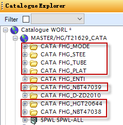
(3) After importing, change the name prefix of components and specifications to the project ProjectCode, replacing the prefix FHG with STT. Renaming avoids conflicts between multiple hanger databases.
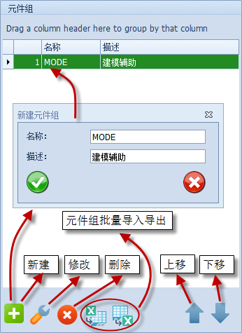
Enter the Design module of the SuppTest project and open and log in to the SolidSupport hanger database management module. Click Database Management in the menu bar and click Reference Components to enter component group and component management. A component group represents a part type, such as equal-leg angle steel, unequal-leg angle steel, channel steel, H-beam, or standard type 2 bolted pipe clamp. Components in a group represent specific specifications, e.g. ANGE(S)-L50X6 is a 50X6 equal-leg angle. You can also build a generic angle part in Paragon using variable parameters and conditional logic.
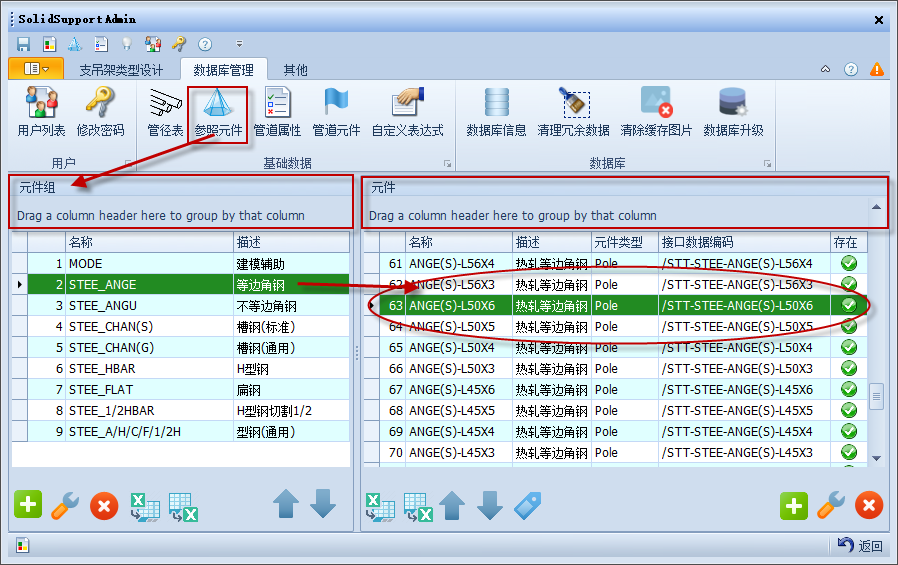
Component groups distinguish component types. Basic operations are create, modify, delete, batch import, batch export, move up, and move down.
(1) Create a component group: click the create button below the component groups, complete the name and description in the dialog box, and click OK. You can keep entering names to create several component groups in a row.
(2) Modify a component group: select the component group, click the modify button below the component groups, and change its name and description in the dialog box.
(3) Delete a component group: select the component group, click the delete button below the component groups, and click OK in the dialog box to delete the group and all its components. This does not delete parts or specification references in the project's Paragon module.
(4) Batch export component groups and components: export the information of the selected component groups (multiple selection allowed) and their components to Excel.
(5) Batch import component groups and components: import component group and component information from Excel into the reference component library. Groups or components with duplicate names are skipped.
(6) Move up and move down: change the order of component groups.
Components are the smallest building blocks of a hanger. They may have specific specifications or be generic, depending on how the part is designed in Paragon. Once created, a component has a unique reference number that is not displayed.
Adding a component while assembling a hanger essentially references its reference number. If you delete a component from the reference component library, hangers that use it lose that component, and creating a new identical component cannot restore it. You must find the hangers that use the component and add the component again.
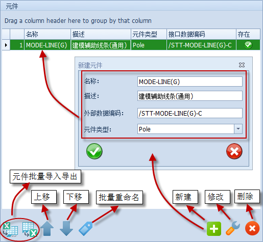
(1) Create a component: click the create button below the components and complete the name, description, external data code, and component type in the dialog box, then click OK. You can keep entering information to create several components in a row. The external data code is the name of the component's specification reference (SPCO) in Paragon; component types are described in section 4.4.3 Component Types.
(2) Modify a component: select the component, click the modify button below the components, and change its name, description, external data code, and component type in the dialog box. Change the external data code and component type with care.
(3) Delete components: select the components to delete (multiple selection allowed) and click the delete button below the components, then click OK in the dialog box.
(4) Batch export components: export the information of the selected components (multiple selection allowed) to Excel. Perform batch operations on component information in Excel, but do not change component names there: the name is the only key for batch operations in Excel, and changing it breaks the link to database data.
(5) Batch import components: import component information from Excel into the reference component library. Components with the same name are refreshed; new components are created.
(6) Move up and move down: change the order of components.
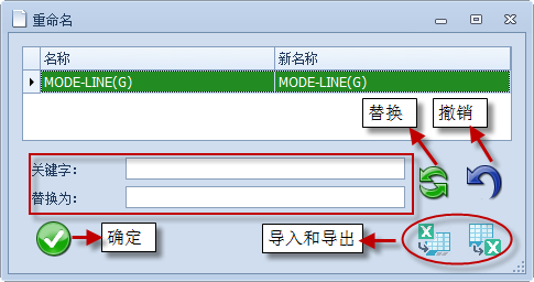
(7) Batch rename: select the components to rename (multiple selection allowed), enter the keyword to change and the replacement in the dialog box, click Replace, then click OK. You can also batch rename in Excel through export and import. Batch rename works the same way in other modules and is not described again.
Component type is SolidSupport's classification of components, based on how they are accounted and how their shape varies.
(1) Pole: a rod whose centerline is a straight line and whose section is extruded, accounted by length.
The component is rod-shaped, used mainly for building steel structures; material quantities are given as a length (mm).
Creation: in Paragon, enter Steelwork mode, click Create in the menu bar, find Category and choose for Profiles…, then design the steel cross-section with PDMS primitives.
(2) Entity: an ordinary part, accounted by count.
The component profile is varied or complex. This type is mainly used to create one-piece parts such as pipe shoes, lifting lugs, hanger plates, curved pad plates, spring components, and pipe clamps. In material take-off, the quantity is counted as a number of pieces (pcs).
Creation method: In the Paragon module, enter Pipework mode. On the menu bar, click Create and find Category…. Then design the part profile using the PDMS primitives.
(3) Plate: A plate part with length and width. All profiles are cut from a rectangle and are calculated by area.
The component profile is simple, generally flat. This type is mainly used to create steel plate parts. In material take-off, the quantity is expressed as an area (mm2).
Creation method: In the Paragon module, enter Pipework mode. On the menu bar, click Create and find Category…. Then design the part profile using the PDMS primitives. For this component type, the first two variable parameters must control length and width. Plate is mainly used to create rectangular plates. To create plates with other profiles (circular, triangular, etc.), make sure the length and width meet the minimum cutting requirements of the profile.
(4) Component type differences
| Component type | Profile feature | Quantity basis | Creation requirement | Parameter requirement |
|---|---|---|---|---|
| Pole (Rod) |
Straight centerline with extruded cross-section. The component is rod-shaped and is mainly used to create structural steel such as angle steel, channel steel, and steel pipe. | Length (mm) | In the Paragon module, enter Steelwork mode. On the menu bar, click Create, find Category, and select for Profiles…. | None |
| Entity (one-piece part) | The component profile is varied or complex. This type is mainly used to create one-piece parts such as pipe shoes, lifting lugs, hanger plates, curved pad plates, spring components, and pipe clamps. | Number of pieces (pcs) | In the Paragon module, enter Pipework mode. On the menu bar, click Create and find Category…. | None |
| Plate (Plate part) |
The component profile is simple, generally flat. This type is mainly used to create steel plate parts. | Area (mm2) | In the Paragon module, enter Pipework mode. On the menu bar, click Create and find Category…. | The first two variable parameters control length and width |
Hanger categories distinguish the different hanger types. For example, HG/T21629-2021 divides supports and hangers into trunnion/leg/lug, auxiliary steel structure, rigid hanger, spring hanger, guide frame, pipe shoe, cold insulation pipe support, high-temperature insulation pipe support, and other types.
(1) Create a hanger category: On the menu bar, click Hanger Type Design, then click Display. In the floating window, click All Categories to return to the Hanger Category interface. In the edit toolbar, click the New button to create a hanger category.
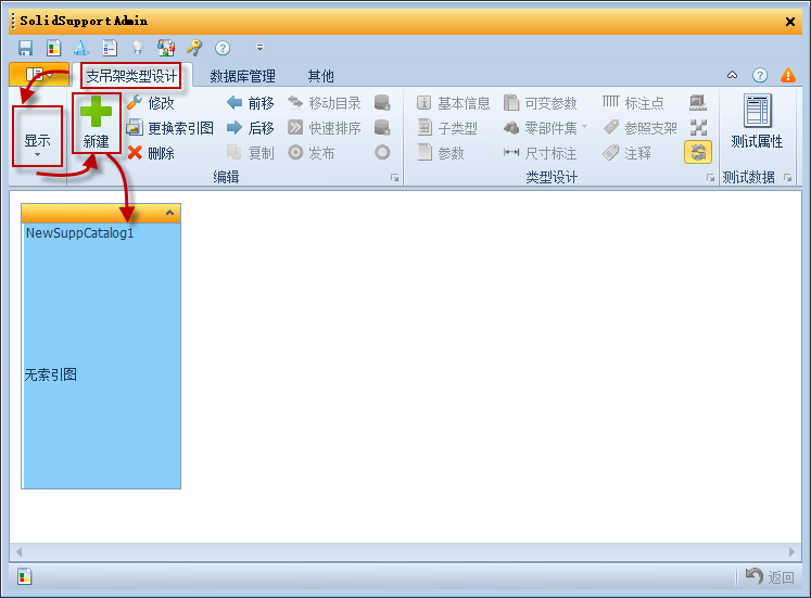
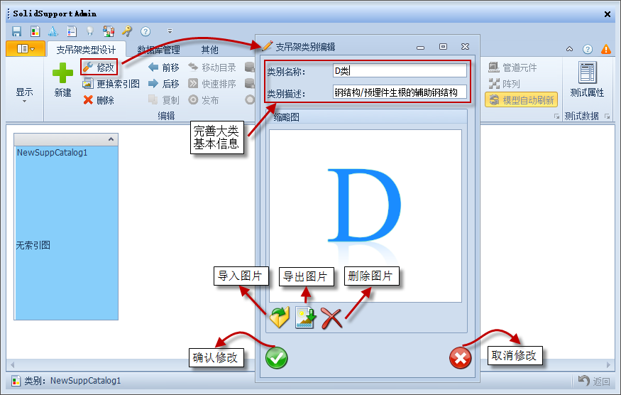
(2) Modify a hanger category: Select the hanger category and click the Modify button in the edit toolbar. In the dialog box, complete the category name, category description, and thumbnail, then click OK to apply the changes.
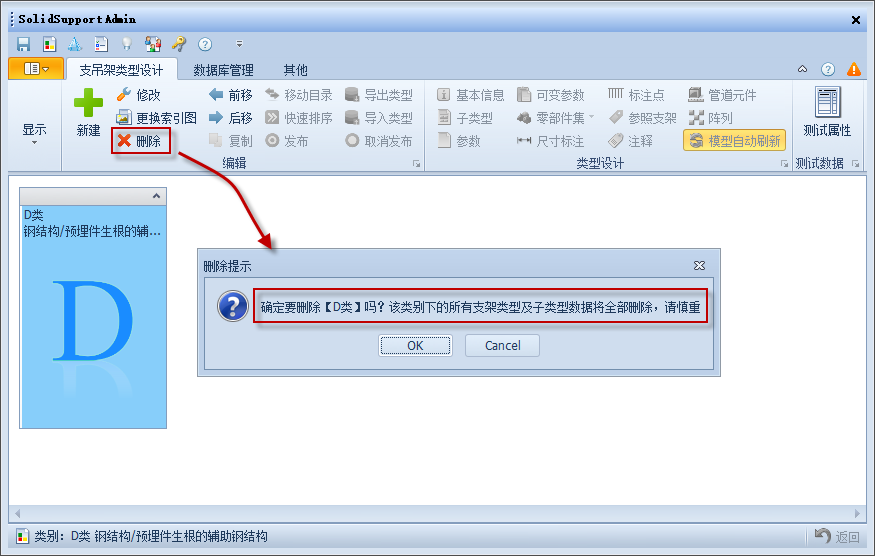
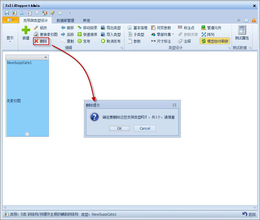
(3) Delete a hanger category: Select the hanger category and click the Delete button in the edit toolbar. After confirming, click OK to delete the category and all hanger types it contains.
A hanger type represents a specific hanger model, such as J1 (welded pipe shoe) and J2 (clamp-type pipe shoe) in HG/T21629-2021.
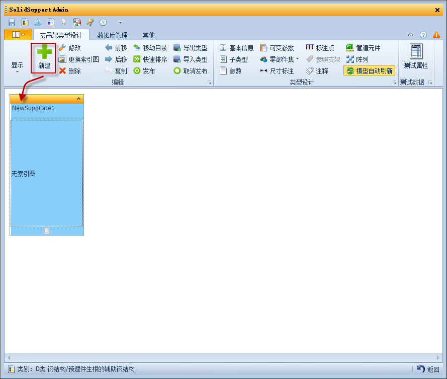
(1) Create a hanger type: Double-click a hanger category to open it, then click the New button in the edit toolbar to create a hanger type.
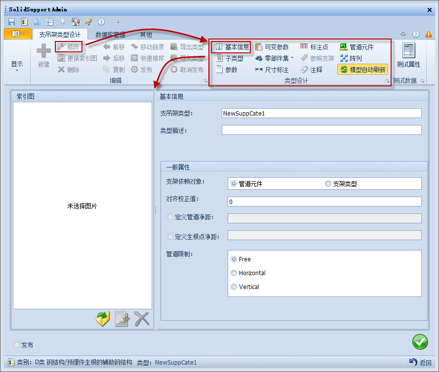
(2) Modify a hanger type: Select a hanger type and click the Modify button in the edit toolbar to enter the hanger type design steps; the Basic Information window opens by default. (Note: You can also double-click the hanger type to open the type design window.)
(3) Delete hanger types: Select the hanger types (multiple selection is allowed) and click the Delete button in the edit toolbar. After confirming, click OK to delete all selected hanger types.
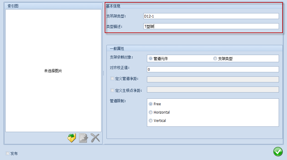
Besides the hanger type name and description, Basic Information also covers the general properties, illustration, and publishing of the hanger type. Select a hanger type and click the Modify button on the type design toolbar, or double-click the hanger type, to open hanger type design.
(1) Basic information: Enter the hanger type and type description. For a new hanger type, simply enter the information given in the catalog.
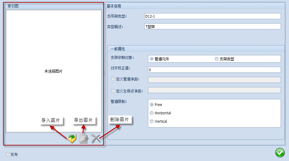
Hanger type: Enter the specific hanger type, such as J1 or J2. You can be more specific if needed; for example, the hanger type in the figure below adds a sub-item, namely D12-1.
Type description: Enter a description of the hanger type, such as welded pipe shoe or clamp-type pipe shoe. In the figure below, the type description is T-frame.
(2) General properties: Define the dependency object, alignment offset, pipe clearance, root clearance, and pipe restriction of the hanger type.
Dependency object: Defines what the hanger type can be added to (pipe component/support type). When a designer uses this support for modeling, if the dependency object is a pipe component, the hanger can be generated by clicking the pipe component; if it is a support type, the hanger can only be generated by adding a sub-support.
Alignment offset: Defines the offset from the ATTA point when the hanger type is axially aligned. Normally, a support and hanger uses the ATTA point as the origin for axial alignment.
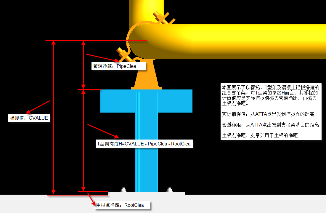
Pipe clearance: Pipe clearance (PipeClea) is the distance from the ATTA point (midpoint of the axis) to the bottom face of the support and hanger. For bare pipe, the pipe clearance is the pipe radius. For a pipe shoe, define it as the distance from the pipe center to the bottom of the shoe; for a trunnion, as the distance from the pipe center to the bottom of the trunnion.
Root clearance: Root clearance (RootClea) is the space occupied by auxiliary root parts such as anchor plates, pad plates, and concrete piers when the support and hanger is rooted. Set the root clearance to the thickness of the auxiliary root part.
As shown below, the pipe shoe defines the pipe clearance and the concrete anchor plate defines the root clearance. When designing a T-frame, allow for this combination: when positioning the structural steel in the T-frame, use the pipe clearance and root clearance in the expression.
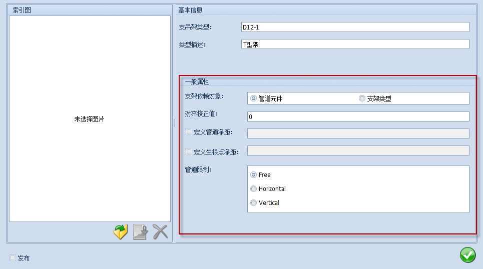
Pipe restriction: Restricts the pipe flow direction to which the hanger type can be added: any, horizontal, or vertical. With the vertical restriction, the centerline of the pipe flow changes to the Z axis, overriding the positioning mode of the part set (see Appendix II, Axis Mode).
(3) Index drawing: Provide an illustration for the hanger type; a resolution of 300*400 or a multiple is recommended.
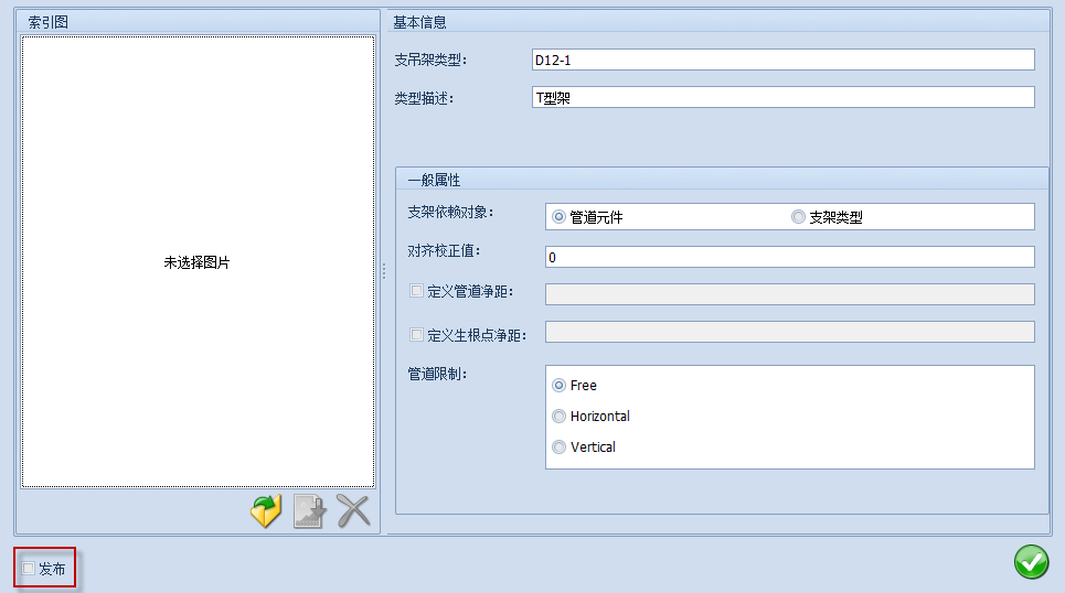
(4) Publish: In the hanger design module, unpublished hanger types can be selected only after logging in with an administrator account. Once a hanger type is customized and tested against the catalog requirements, it can be published.
Hanger subtypes can be divided by pipe diameter, structural steel specification, hanger sub-item, and so on. After the basic information of the hanger type is in place, click Subtype on the type design toolbar to open the subtype design window.
Design subtypes together with part sets: a subtype can use only one part set. Having several subtypes share one part set complicates later maintenance and changes, so a one-to-one mapping between subtypes and part sets is recommended.
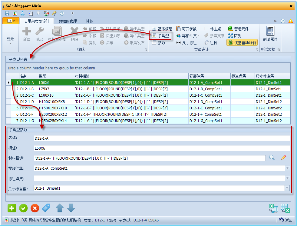
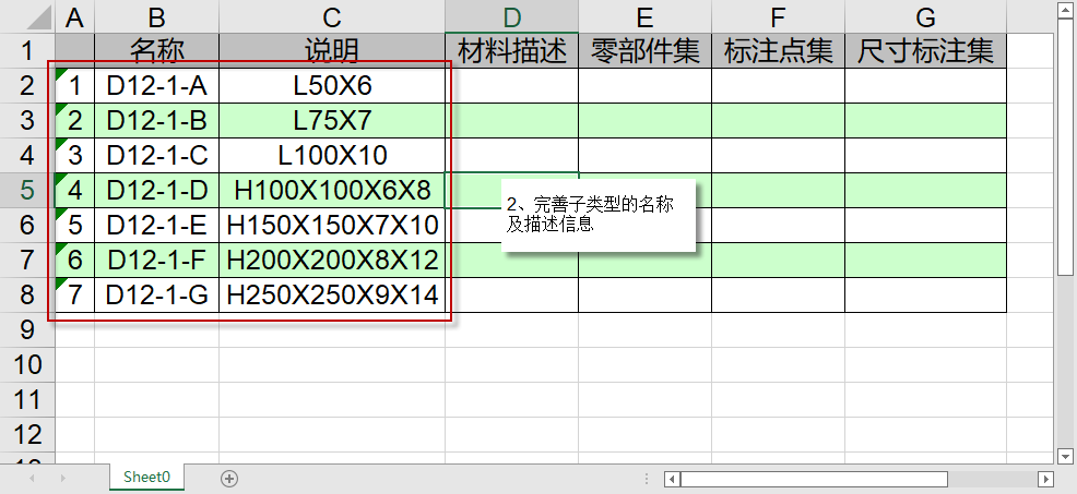
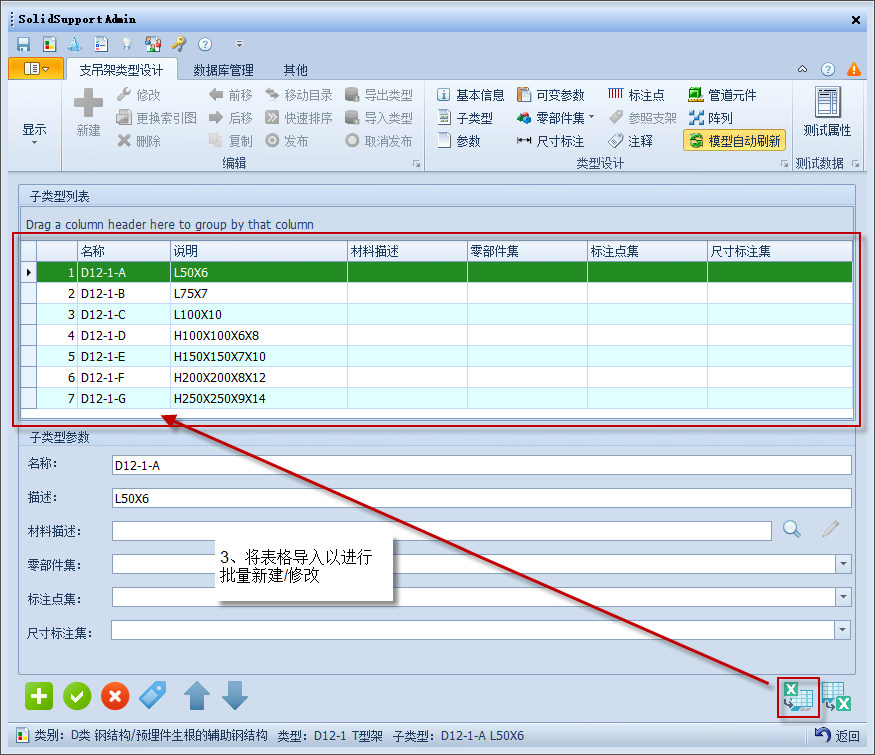
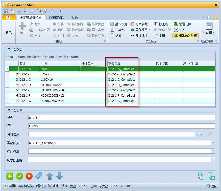
(1) Create subtypes: According to the drawing, D12-1 is divided into 7 sub-items by structural steel specification, so you can create 7 subtypes. Because no part sets, annotation point sets, dimension sets, or parameters have been created yet, you only need to complete the subtype name and description. Follow the figure below.
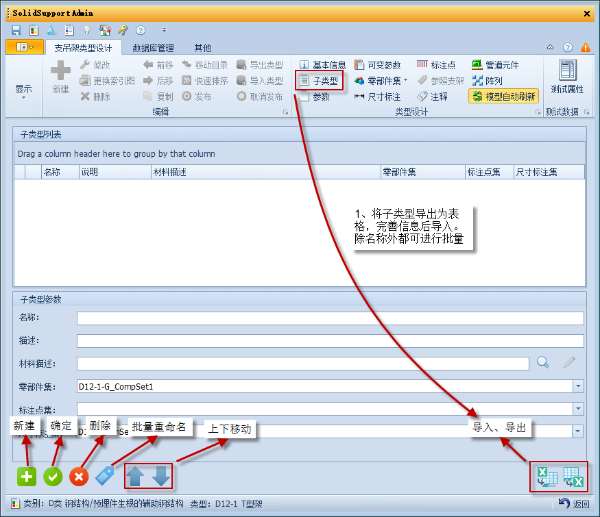
Fill in the subtype information in the exported table as shown below.
After completing the table, import it to create the hangers in batch (the same table can also update them in batch, except for the hanger names).
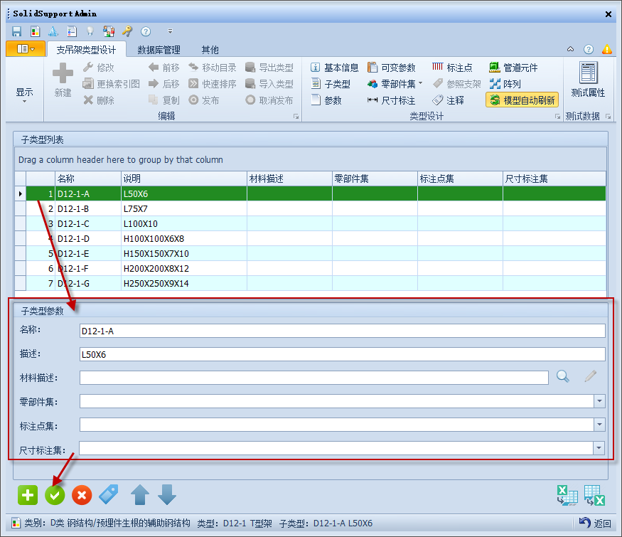
(2) Modify subtypes: Besides editing subtype information in the table, you can also modify it in the subtype parameter interface. Select the subtypes to change, make the changes, and click OK.
A part set is a collection that holds parts. Each subtype corresponds to one part set, and you add parts to the part set to design the hanger in detail. On the type design toolbar, click Part Set and select Part Set Management to open the Part Set Management window.
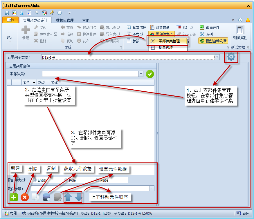
(1) Create a part set: Click Part Set Management and create the part set in the dialog box. Make sure to select the correct positioning mode: the part set positioning mode determines the axis mode of the hanger (see Appendix II, Axis Mode).
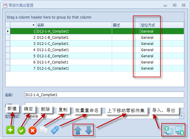
(2) Complete the part set information for the subtypes: You can set it one by one in the Part Set Management interface, or return to the subtype interface and set the part set information for each subtype. Export the subtype information to a table, add the part set information, and import the table to link subtypes to part sets, as shown below.
Parameters are not visible to designers in the hanger design module and cannot be changed. They store fixed parameter values of a subtype. For D12-1, for example, each subtype corresponds to a specific structural steel specification; the steel profile data is needed later to position the steel, so it can be stored in parameters.
Parameters can also set default, maximum, and minimum values for different subtypes and flag subtypes. They can likewise be exported to a table, edited there, and imported back. Complete the parameter design for hanger D12-1 using the data in the figure below:
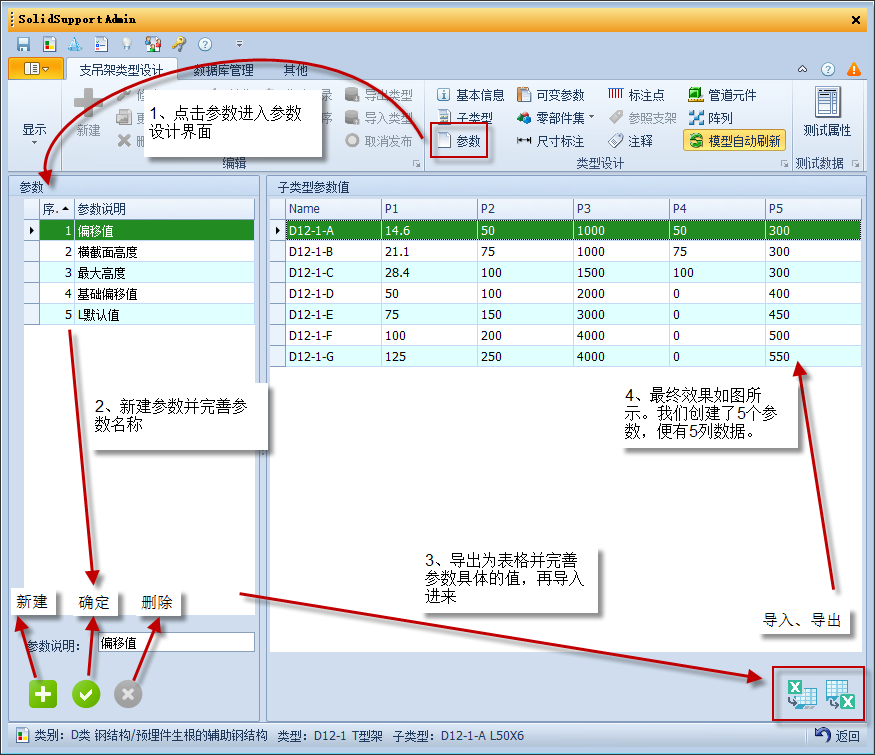
When used, parameters are referenced as PARAM[X], where X is the parameter index. To use the second parameter (cross-section height) to move the structural steel, for example, use PARAM[2].
For details on expressions in SolidSupport, see Appendix I, Common Expressions.
If a variable parameter is not set to be hidden in the front end, it appears in the dialog box when you click Modify Hanger in the hanger design module. Designers can then change the parameter value or option to adjust the hanger length, height, material, model matching, and so on. On the type design toolbar, click Variable Parameter to open the variable parameter editor, click the New button, select a variable parameter type, and click OK to create a variable parameter.
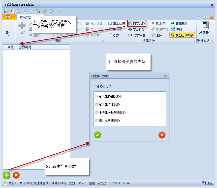
SolidSupport currently defines four variable parameter types: input numeric parameter, input text parameter, subtype-associated list parameter, and expression list parameter. Besides the three basic properties (index, front-end hidden, and parameter description), each type has its own special properties.
(1) Input numeric parameter: The data type is numeric and can be used in mathematical calculations. Its special properties are default value, maximum, minimum, graphical interaction, smart sensing, calculated value, prompt, direction, and interaction prompt.
Input numeric parameter
| Special property | Property description |
|---|---|
| Default value | Defines the default value of the variable parameter |
| Maximum | Defines the maximum value of the variable parameter |
| Minimum | Defines the minimum value of the variable parameter |
| Graphical interaction | Defines the graphical interaction mode used when snapping the variable parameter; if set to None, snapping is not available. |
| Smart sensing | When selected and an auxiliary modeling part is set, automatically calculates the distance from the ATTA point to the contact face. |
| Calculated value | Processes the snap value of the graphical interaction |
| Prompt | Prompt shown when the parameter is used |
| Direction | Defines the snapping direction of the variable parameter; only one of the 6 available directions can be selected. |
| Interaction prompt | Each graphical interaction mode has its own interaction prompt; this option cannot be changed. |
When used, input numeric parameters are referenced as DESP[X], where X is the parameter index. To use the first input numeric parameter, for example, use DESP[1].
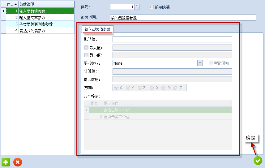
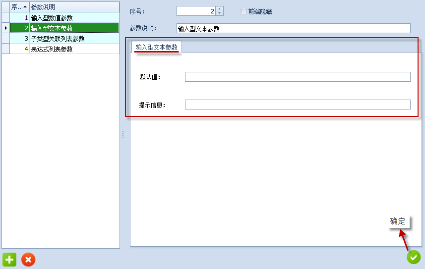
Input text parameter
| Special property | Property description |
|---|---|
| Default value | Defines the default value of the variable parameter |
| Prompt | Defines the prompt shown when the variable parameter is used |
When used, input text parameters are referenced as DESP[X], where X is the parameter index. To use the second input text parameter, for example, use DESP[2].
(3) Subtype-associated list parameter: The data consists of keys and values, called key-value pairs. The key is text and must be unique; the value is numeric and may repeat. For a given set of key-value pairs, associations can be set per subtype.
To use a key, reference it as DKEY[X], where X is the parameter index. To use the key in the third subtype-associated list parameter, for example, use DKEY[3].
To use a value, reference it as DESP[X], where X is the parameter index. To use the value in the third subtype-associated list parameter, for example, use DESP[3].
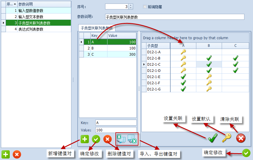
As shown above, for subtype D12-1-B, variable parameter 3 defaults to key A and can be freely chosen among keys A, B, and C; subtype D12-1-A can use only the default key A. This shows how closely a subtype-associated list parameter is tied to its subtype.
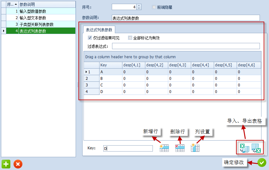
(4) Expression list parameter: The data structure is a list, i.e., a two-dimensional structure of rows and columns, with keys in the first column. Data types are string, double, integer, and Boolean. A filter expression restricts which rows can be selected.
Expression list parameter
| Special property | Property description |
|---|---|
| Only filtered results visible | In the hanger design module, only rows matching the filter expression are visible. |
| Mark all as valid | In the hanger design module, selecting rows outside the filter results does not raise an error. |
| Filter expression | Uses an expression to select the qualifying rows |
| Visible in column settings | Controls column visibility in the hanger design module |
To use a key, reference it as DKEY[X], where X is the parameter index. To use the key in the fourth expression list parameter, for example, use DKEY[4].
To use a value, reference it as DESP[X,Y], where X is the parameter index and Y is the column index. To use the value in the fifth column of the fourth expression list parameter, for example, use DESP[4,5].
(5) Complete the variable parameter design for hanger D12-1 as shown below. The catalog shows that two input numeric parameters are needed to control dimension L and dimension H.
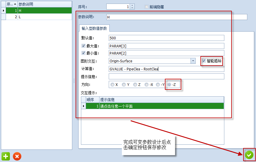
Dimension H: Dimension H is the height of the T-frame. Set the default to 500, the maximum to parameter 3 (maximum height), the minimum to parameter 2 (cross-section height), the graphical interaction to point-to-face (from the ATTA point to a contact face) with smart sensing enabled, the calculated value to the snap value minus the pipe clearance and then minus the root clearance, and the snapping direction to -Z.
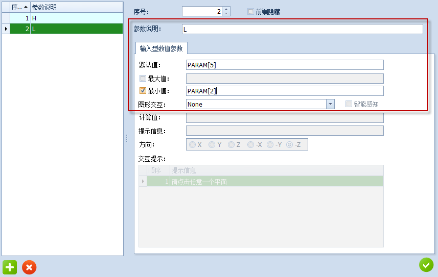
Dimension L: Dimension L is the arm length of the T-frame. Set the default to parameter 5 (L default) so that each subtype gets its own default arm length, leave the maximum empty, set the minimum to parameter 2 (cross-section height), and leave the graphical interaction empty.
Most of the hanger design work is done here. Hanger assembly usually involves modifying or adjusting parameters, variable parameters, subtypes, and part positioning/properties until the catalog requirements are met.
Before assembling the hanger, open Part Set Management and select the hanger subtype there. For the selected part set, add parts and complete their properties. Part properties consist of general properties, position properties, angle properties, size properties (Plate only), component variable parameters, and custom expressions. The properties of each part type are described below.
(1) Entity (one-piece part)
Entity (one-piece part)
| Property category | Property | Description |
|---|---|---|
| General properties | Component reference | Select a reference component of component type Entity (one-piece part) |
| Name | Defines the part name | |
| Material code | Defines the part material code. In the Paragon module, insert the custom attribute SDSMaterial into the SDTE referenced by the component specification. | |
| Variable parameter | Used only by auxiliary modeling parts; defines the input numeric parameters that require smart sensing | |
| Array | Defines the array pattern of the part; create the array first, then select it here. | |
| Exclude from material | When selected, the part is not counted in material summaries or the hanger schedule. | |
| Position properties | Position | The position properties of an Entity consist of X, Y, and Z only, defining the part position. |
| Angle properties | Rotation | Defines the rotation angle of the Entity |
| Component variable parameter | Component variable parameter | Component variable parameters correspond one-to-one to the variable parameters defined for the part in the Paragon module. Select the part, click Modify on the PDMS menu bar, and then click Properties… to open the part property list; create one parameter expression for each property. |
| Custom expression | Custom expression | Defines part details such as material, specification, standard number, part type, series number, and description. Define the custom expressions globally first, then complete the part information here. The values can also be extracted for later reports. |
(2) Pole (rod)
Pole (rod)
| Property category | Property | Description |
|---|---|---|
| General properties | Component reference | Select a reference component of component type Pole (rod) |
| Name | Defines the part name | |
| Material code | Defines the part material code. In the Paragon module, insert the custom attribute SDSMaterial into the SDTE referenced by the component specification. | |
| Variable parameter | Used only by auxiliary modeling parts; defines the input numeric parameters that require smart sensing | |
| Array | Defines the array pattern of the part; create the array first, then select it here. | |
| Exclude from material | When selected, the part is not counted in material summaries or the hanger schedule. | |
| Position properties | Position Start | Defines the start position of the Pole |
| Position End | Defines the end position of the Pole | |
| Vector Start | Defines the cut angle at the start of the Pole | |
| Vector End | Defines the cut angle at the end of the Pole | |
| Angle properties | Angle | Defines the rotation angle of the Pole about its centerline |
| Component variable parameter | Component variable parameter | Component variable parameters correspond one-to-one to the variable parameters defined for the part in the Paragon module. Select the part, click Modify on the PDMS menu bar, and then click Properties… to open the part property list; create one parameter expression for each property. |
| Custom expression | Custom expression | Defines part details such as material, specification, standard number, part type, series number, and description. Define the custom expressions globally first, then complete the part information here. The values can also be extracted for later reports. |
(3) Plate (plate part)
Plate (plate part)
| Property category | Property | Description |
|---|---|---|
| General properties | Component reference | Select a reference component of component type Plate (plate part) |
| Name | Defines the part name | |
| Material code | Defines the part material code. In the Paragon module, insert the custom attribute SDSMaterial into the SDTE referenced by the component specification. | |
| Variable parameter | Used only by auxiliary modeling parts; defines the input numeric parameters that require smart sensing | |
| Array | Defines the array pattern of the part; create the array first, then select it here. | |
| Exclude from material | When selected, the part is not counted in material summaries or the hanger schedule. | |
| Position properties | Position | The position properties of a Plate consist of X, Y, and Z only, defining the part position. |
| Angle properties | Rotation | Defines the rotation angle of the Plate |
| Size properties | Size | Defines the length and width of the Plate (the first two variable parameters defined for a plate in the Paragon module must be length and width). |
| Component variable parameter | Component variable parameter | Component variable parameters correspond one-to-one to the variable parameters defined for the part in the Paragon module. Select the part, click Modify on the PDMS menu bar, and then click Properties… to open the part property list; create a parameter expression for each remaining property except length and width. |
| Custom expression | Custom expression | Defines part details such as material, specification, standard number, part type, series number, and description. Define the custom expressions globally first, then complete the part information here. The values can also be extracted for later reports. |
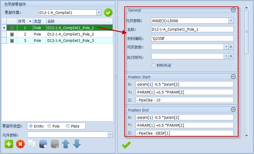
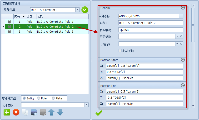
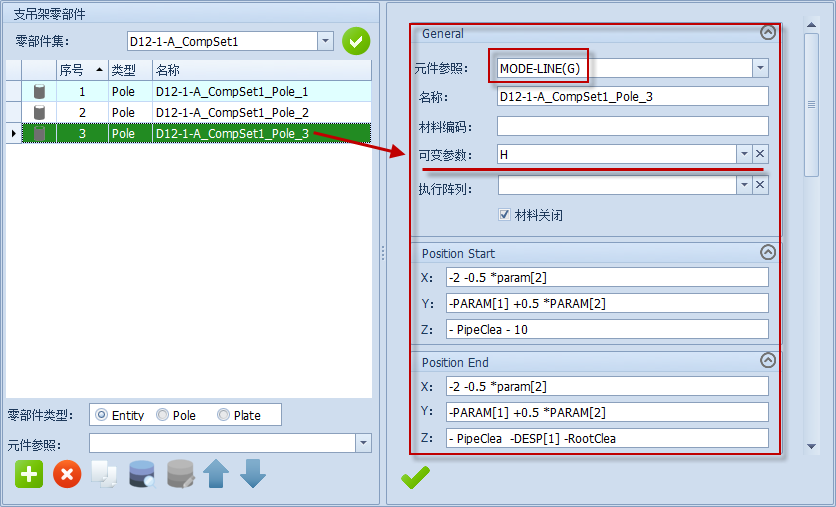
(4) Complete the part design for subtype D12-1-A as shown in the figure. Set only the properties shown; leave the others unset. It is advisable to click OK after entering each property to watch the part move.
T-frame leg: First define the Z coordinate in the position properties so the structural steel profile becomes visible.
T-frame cantilever: First define the Y coordinate in the position properties so the structural steel profile becomes visible.
Auxiliary modeling line: This part is mainly used for smart sensing. It senses the contact face in the extension direction of the part and returns the distance to the assigned variable parameter. The auxiliary modeling line is a Pole whose two ends are the fixed end and the sensing end. The fixed end has a fixed position and does not affect the result, as shown by Position Start in the figure below. The sensing end has a variable position and must contain the associated variable parameter, as shown by Position End in the figure below.
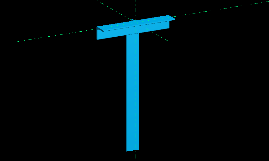
After designing these three parts, the hanger subtype D12-1-A is initially complete. In the PDMS view, the hanger should look like the figure below.
The Batch Management interface lets you quickly add parts to a part set and set part properties in batch. On the type design toolbar, click Part Set and select Batch Management to open it.
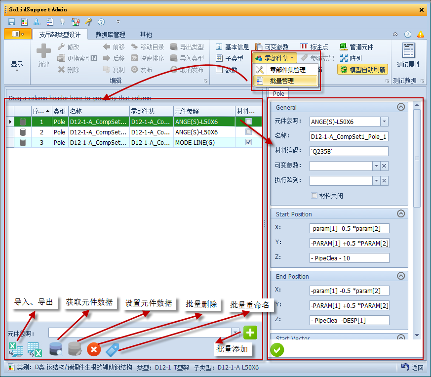
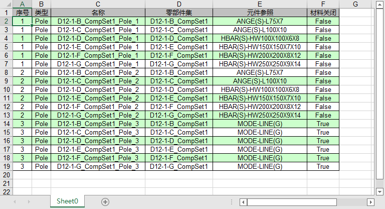
(1) Import parts in batch: Use the Excel import and export functions to add parts to a part set in batch. Prepare the table as shown below and import it into the Batch Management interface. Do not import existing parts again, or their properties will be cleared!
The result after import is shown below.
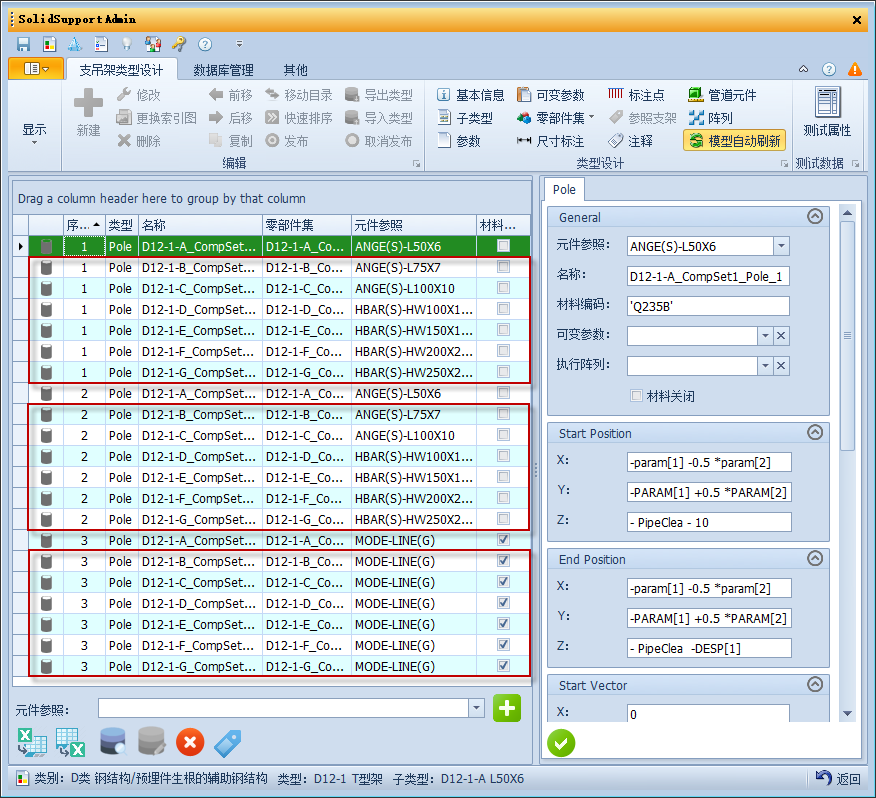
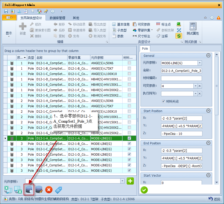
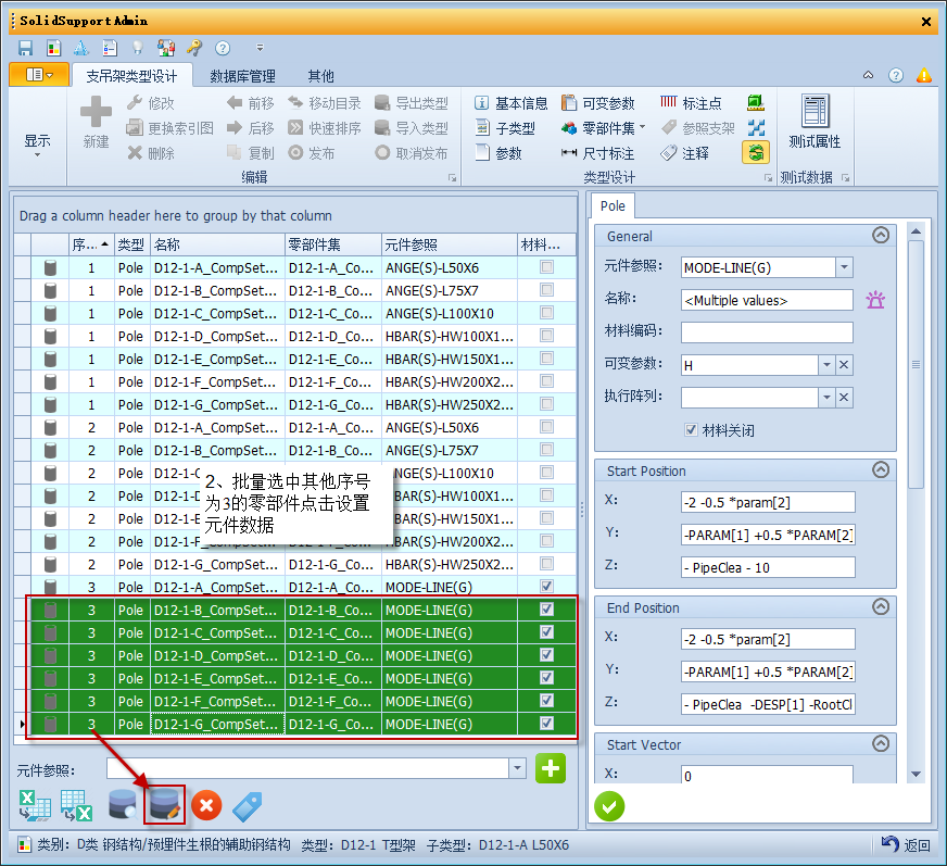
(2) Set parts in batch: To set properties for all parts with index 3, first select part D12-1-A_CompSet1_Pole_3 and click Get Component Data, then select the other parts with index 3 and click Set Component Data.
(3) Modify the other parts: because the parts numbered 1 and 2 reference different components in different hanger subtypes, their movement schemes, that is their parameter expressions, may well differ. In this case, return to Part Set Management and configure the parts for each subtype.
On closer inspection, you only need to adjust the part properties in hanger subtype D12-1-D, because types A-C are all angle steel and types D-G are all H-beams. Then repeat step 2 to batch-set the part properties of types B-C and types E-G.
Dimensions let you see hanger parameter changes intuitively. On the Type Design toolbar, click Dimensions to open the dimension editing interface.
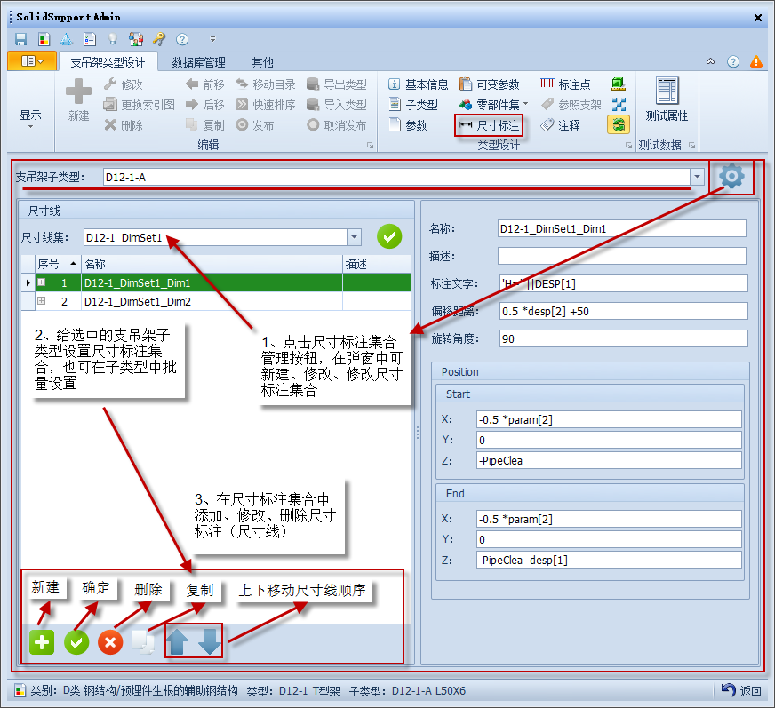
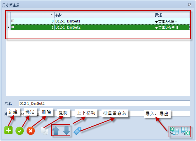
(1) Create a dimension set: click the Dimension Set Management button and add a dimension set in the dialog box, as shown below.
(2) Complete the dimension set information for the subtypes: you can set it one by one in the dimension interface, or return to the subtypes and assign the corresponding dimension set to each subtype. Export the subtype information to a table, fill in the dimension set information, and import the table to link the subtypes to the dimension set, as shown below.
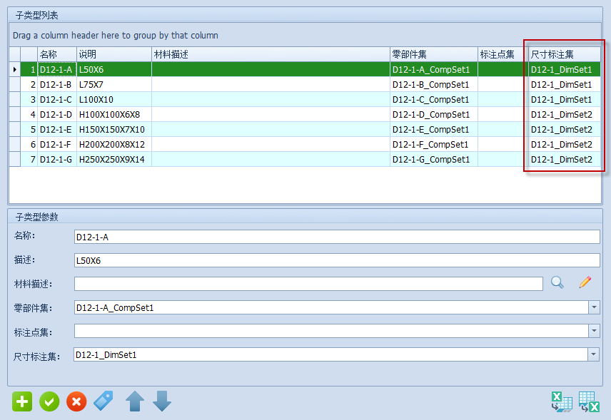
Note that subtypes A-C and subtypes D-G are linked to different dimension sets.
(3) Add dimension lines: once the subtypes are linked to the dimension set, click Dimensions, add dimension lines for subtype D12-1-A, and set their properties.
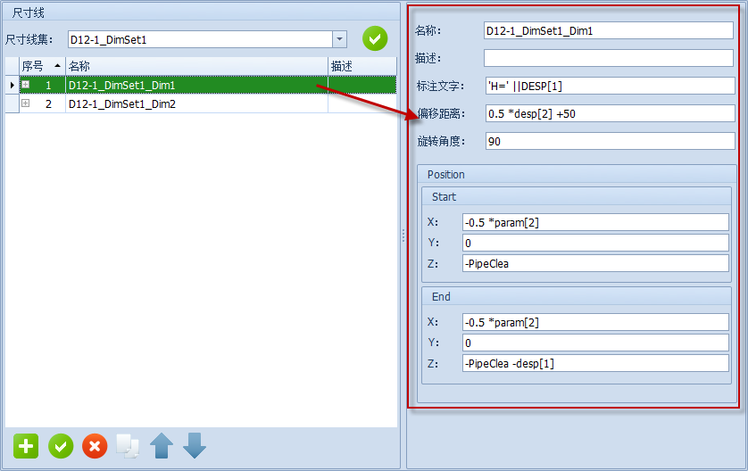
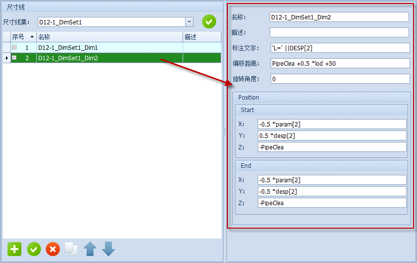
When you are done, the PDMS view should look like the figure below. Complete the dimensions for the remaining subtypes according to the drawing requirements.
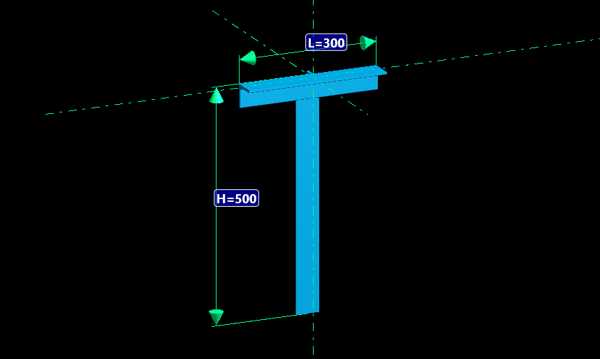
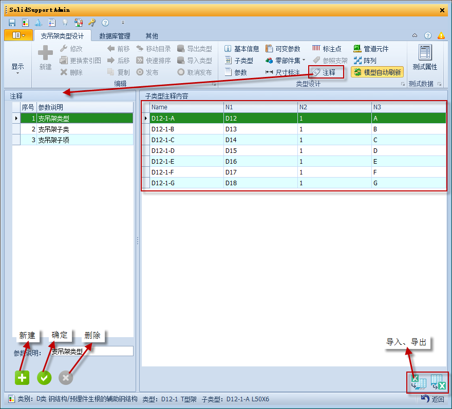
Each hanger has a corresponding hanger code (in SolidSupport this is the material description of the subtype). You can enter regularly patterned text in the notes, then complete the material description of the hanger subtype in the subtype form.
(1) Add notes: on the Type Design toolbar, click Notes to open the note editing interface. Add the notes as shown in the figure below. To use a note, reference it as NOTE[X], where X is the note number.
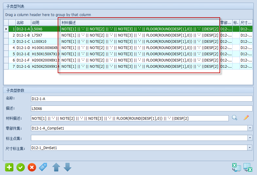
(2) Complete the subtype material description as shown in the figure below.
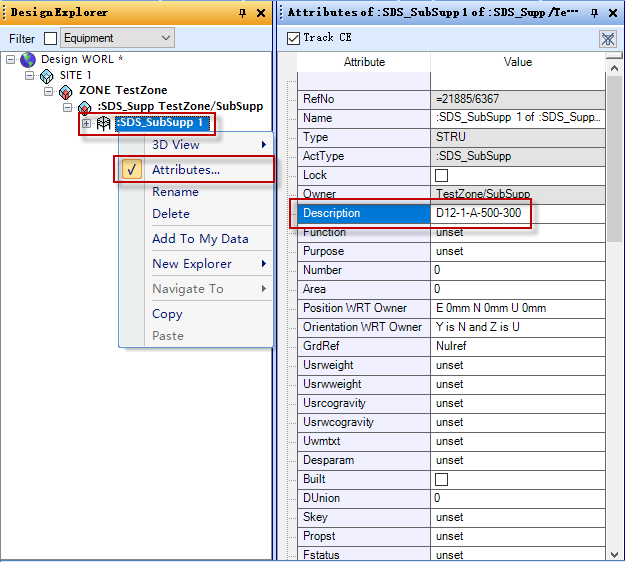
(3) Check the material description: in the PDMS tree view, find :SDS_SubSupp 1, right-click Attributes... to open the attribute list, and check whether the material description in the Description column is correct.
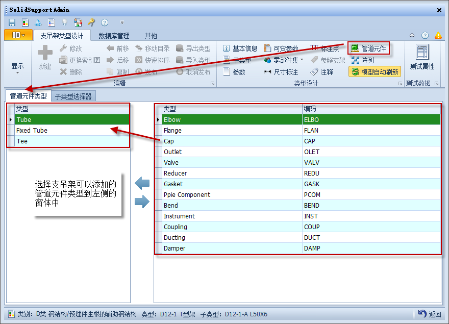
Select the piping component types to which this hanger can be added, and set the condition limits in the subtype selector.
(1) Add piping components: a T-frame can be added to pipes, fixed-length pipes, and tees.
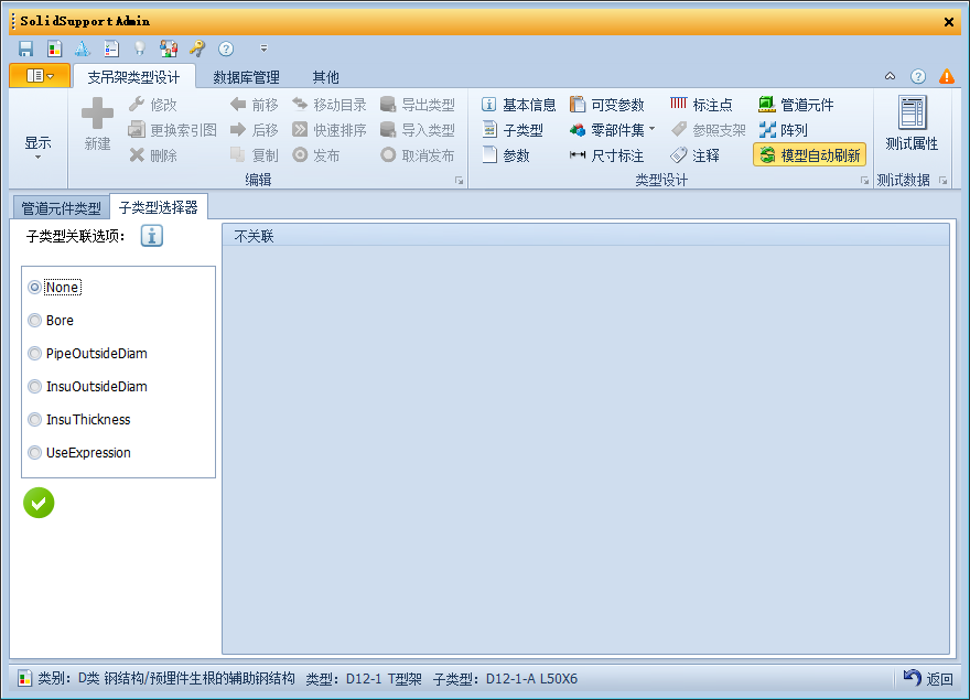
(2) Subtype selector: D12 (T-frame) does not need a subtype selector. The subtype selector is described below.
Subtype Selector
| Option | Description |
|---|---|
| None | No restriction on hanger placement other than the component type |
| Bore | Limits the pipe diameter range the subtype can be added to |
| PipeOutsideDiam | Limits the pipe outside diameter the subtype can be added to |
| InsuOutsideDiam | Limits the insulation outside diameter the subtype can be added to |
| InsuThickness | Limits the insulation thickness the subtype can be added to |
| UseExpression | Defines a custom piping limit for the hanger by expression, e.g. BORE >= 50 AND BORE <= 600 AND INSU > 20 |
The interface is shown below:
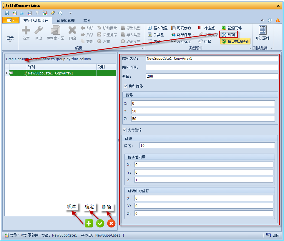
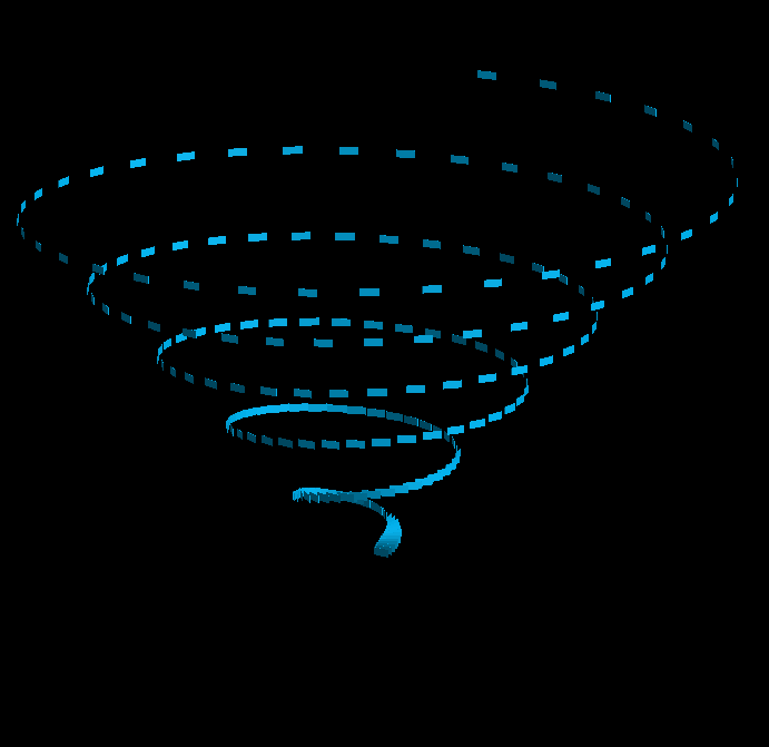
Arrays are mainly used to design hanger types whose part quantity is controlled by parameters. For a multi-level portal frame, for example, you can use an array to design the number and spacing of the portal frame beams. This feature is explained below using a rising spiral structure as an example. The array properties are listed in the table below:
Array
| Property | Description |
|---|---|
| Array name | Defines the array name |
| Array description | Defines the array description |
| Quantity | Defines the number of array instances (excluding the first array item) |
| Perform Offset | Defines the offset of the component during arraying; the X, Y, and Z offsets can be set |
| Perform Rotation | Defines the rotation of the component during arraying; the rotation angle, rotation axis vector, and rotation center coordinates can be set |
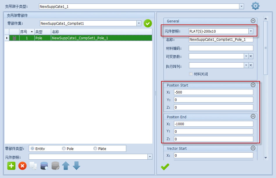
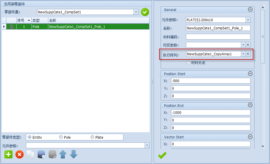
(1) Create a hanger subtype and then a new part set. After setting the part set in the subtype, add a flat steel part to the part set with the properties below. Only the profile is needed; leave the other properties unset for now.
(2) Create an array: on the Type Design toolbar, click Arrays, create an array, and set the properties as shown in the figure below.
(3) Set the array reference: return to Part Set Management and set the array reference for the part.
(4) Check the result
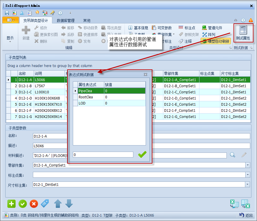
While designing a hanger type, you often need to test the referenced piping properties to check whether the expressions you entered are correct, or whether part profiles, position changes, and material descriptions are correct. Click the Test Properties button on the Test Data toolbar to test the properties referenced by the current hanger.
This feature is retained from SolidSupport Hanger Design V1.0 and is not recommended for current hanger design work.
A reference support is a hanger designed to be linked to another hanger type. The linked hanger type is called the referenced support, and the hanger that links to another hanger type is called the reference support. A reference support can read parameters, variable parameters, part properties, and other data from the referenced support during its design.
(1) Define a reference support: create a hanger type and complete its basic information in the basic information interface. Change the support dependency object to Support Type, click OK to save the change, return to the hanger category, and re-enter the hanger type. The Reference Support button on the Type Design toolbar then becomes available.
Note that once the support dependency object is changed to Support Type, the hanger is no longer related to piping components.
Before the following demonstration, create a few subtypes first.
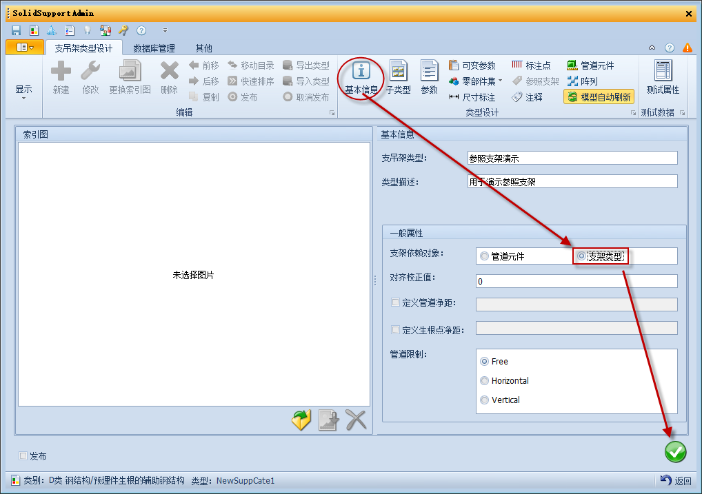
(2) Link types: on the Type Design toolbar, click Reference Support to open the editing interface, which opens on the link type interface by default. Select the hanger type to link and click OK to complete the link.
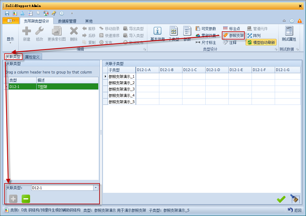
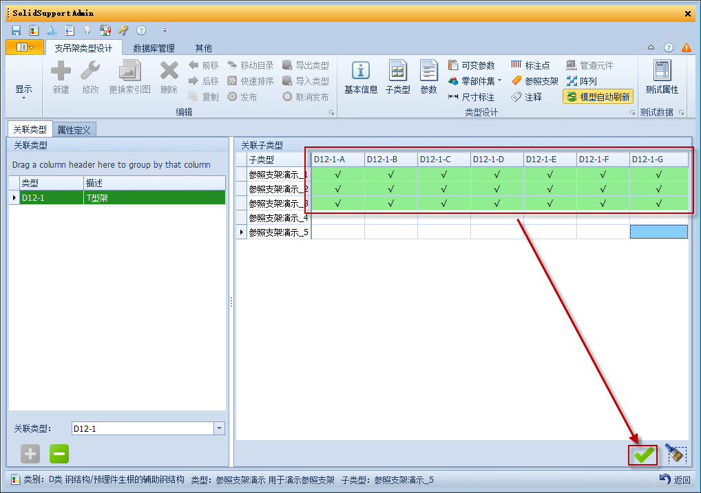
(3) Link subtypes: link the subtypes of the reference support and the referenced support. Only after linking can you add the reference support to the referenced support in the hanger design module. As shown in the figure below, subtypes 1-3 of the reference support are linked to subtypes in D12-1.
(4) Reference properties: click Property Definition to open the reference property settings, where you specify the data the reference support retrieves from the referenced support. Then select the link type in the property expression and enter the expressions in order. For the expression format, see (3) Reference support keywords in Appendix 1, Common Expressions.
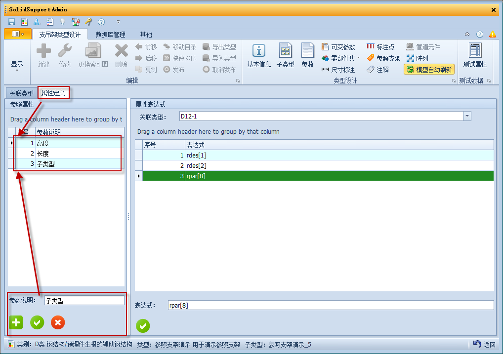
(5) Use reference properties: a defined reference property is referenced as ratt[X], where X is the sequence number of the reference property. To use the second reference property, Length, reference it as ratt[2].
After the hanger is designed, add and modify actual hangers to test it and analyze whether it meets the requirements of the standard drawing set and of the designers. If you are adding hangers to a project for the first time, configure the database first: reference the DB of the SolidSupport basic property library and the DB of the hanger database in the test project, and add them to the MDB.
After setting the project path, you only need to be able to read the SolidSupport basic property library and the hanger database, as shown below
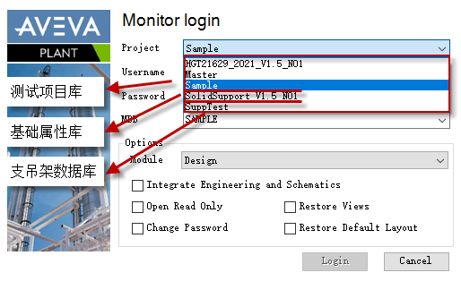
Using the Sample project as the test project, enter the Admin module and Include the DBs in SolidSupport_V1.5_NO1 and SuppTest into the database (note that the DB used for hanger testing in SuppTest does not need to be Included), then add them to the design MDB, as shown below
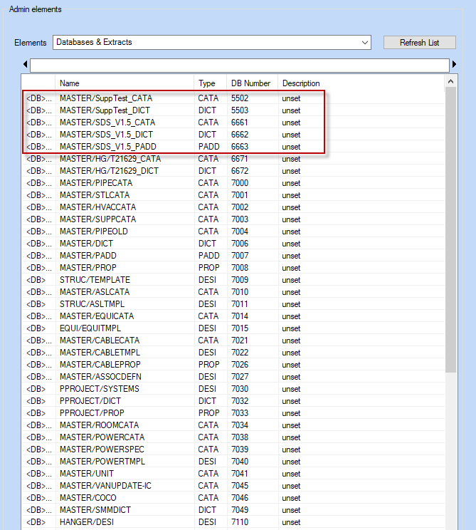
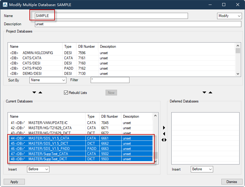
Log in to the Design module of the test project, click BopoodTech on the PDMS menu bar, and select Hanger Design under SolidSupport to test hangers.
The test covers whether hanger types can be added normally, whether component limits are correct, whether parameter changes meet requirements, whether snapping works, whether smart sensing works, whether dimensions are correct, and whether the hanger code and part materials are correct.
Modify the hanger according to the standard drawing set or design requirements. During testing, you can take screenshots of the actual hanger to improve the illustration information. The optimization process repeats the operations in Sections 4.2-4.7.
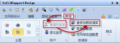
After modifying and saving a hanger in the hanger database management module, log in to the hanger design module with an administrator account and click Reload Database to pick up the updated database immediately.
Database Management lets you modify users, basic data, and database information. Click Database Management on the menu bar to open it.
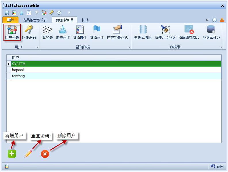
On the User toolbar, click User List. In the user list you can create users, reset passwords, and delete users.
Omitted.
The pipe diameter table only defines the range of Bore (nominal diameter) in the subtype selector. SolidSupport includes common pipe diameters from DN6 to DN2000, and you can add more as needed.
Do not exceed the pipe diameter range of ATTA in the SolidSupport basic property library. The ATTA pipe diameter range in the basic property library is DN6 to DN4000, as listed in the table below:
| DN6 | DN8 | DN10 | DN15 | DN20 | DN25 | DN32 | DN40 |
|---|---|---|---|---|---|---|---|
| DN50 | DN65 | DN80 | DN90 | DN100 | DN125 | DN150 | DN200 |
| DN250 | DN300 | DN350 | DN400 | DN450 | DN500 | DN550 | DN600 |
| DN650 | DN700 | DN750 | DN800 | DN850 | DN900 | DN950 | DN1000 |
| DN1050 | DN1100 | DN1150 | DN1200 | DN1250 | DN1300 | DN1350 | DN1400 |
| DN1450 | DN1500 | DN1550 | DN1600 | DN1650 | DN1700 | DN1750 | DN1800 |
| DN1850 | DN1900 | DN1950 | DN2000 | DN2050 | DN2100 | DN2150 | DN2200 |
| DN2250 | DN2300 | DN2350 | DN2400 | DN2450 | DN2500 | DN2550 | DN2600 |
| DN2650 | DN2700 | DN2750 | DN2800 | DN2850 | DN2900 | DN2950 | DN3000 |
| DN3050 | DN3100 | DN3150 | DN3200 | DN3250 | DN3300 | DN3350 | DN3400 |
| DN3450 | DN3500 | DN3550 | DN3600 | DN3650 | DN3700 | DN3750 | DN3800 |
| DN3850 | DN3900 | DN3950 | DN4000 |
The Code field of the pipe diameter table can be left blank; it is reserved for version information.
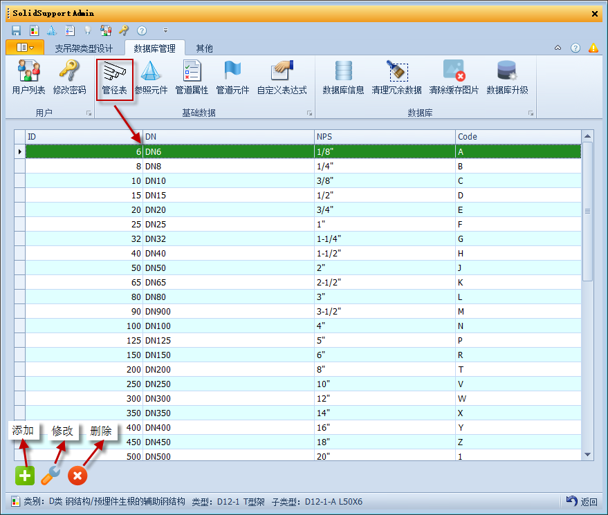
See Section 4.4, Creating a Reference Component Library.
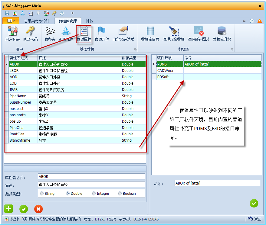
Piping properties are a set of pipe-related properties. They are not limited to pipes or the ATTA on pipes; they can also be various properties of Branch, Pipe, Site, and so on. Piping properties can be used for mathematical calculations, information display, and condition evaluation.
Piping properties can be mapped to different 3D plant software environments. The built-in piping properties currently include interface commands for PDMS and E3D.
(1) Default piping properties: the software includes some common piping properties, which can be called with property expressions anywhere an expression can be entered, as shown below
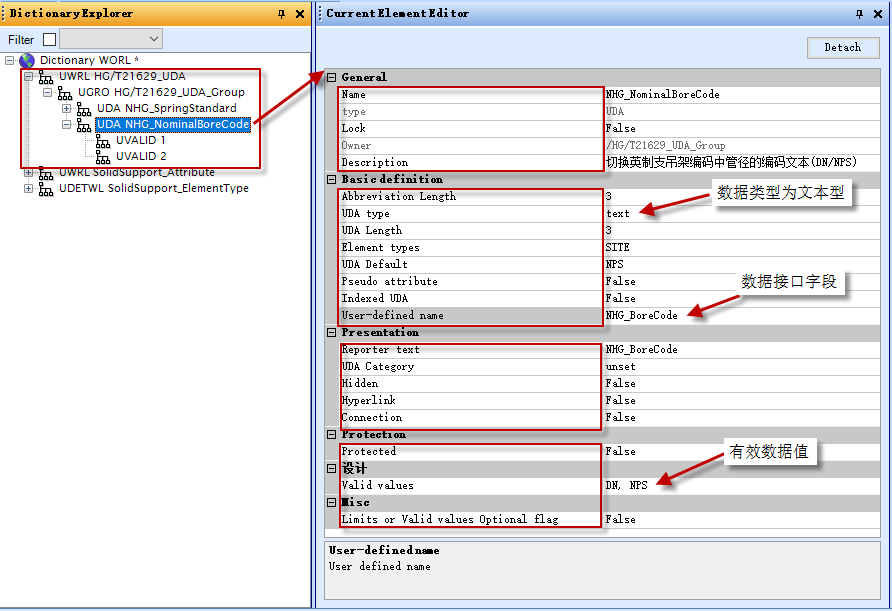
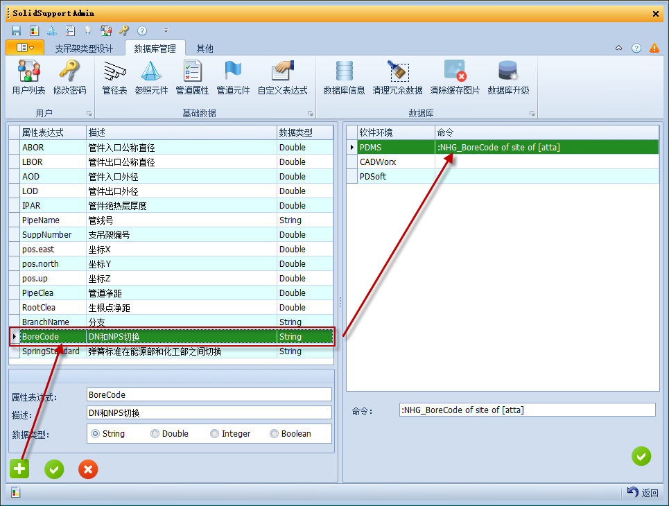
(2) Custom piping properties: you can also add custom UDAs in the Lexicon module of the hanger database, then create a new piping property and enter the interface command to establish the connection. The following example uses DN/NPS switching in the HG/T21629-2021 hanger database.
Start PDMS, enter the Lexicon module of the hanger database, and create the UDA :NHG_NominalBoreCode at the following level. Complete the properties shown in the figure below. Note that the User-defined name property is the interface field.
Create a new piping property and set the interface command, and it can then be used in expressions, as shown below:
Piping components define the objects to which hangers can be added; you can also add your own as needed. Click Piping Components to open Piping Component Management. The default piping components are as follows:
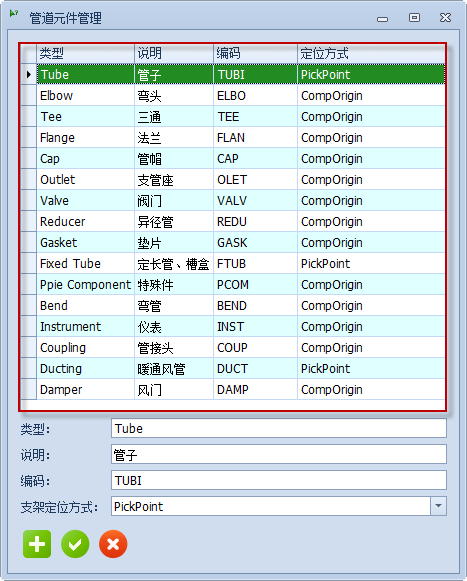
(1) Component code: each piping component type has a corresponding code in the plant design software. When a hanger is added, the program checks whether the piping component code allowed for the hanger matches the code defined in the plant design software; if they do not match, the hanger cannot be added.
(2) Positioning method: there are two methods, pick point (PickPoint) and component origin (CompOrigin). Piping components such as pipes and fixed-length pipes should use pick point positioning, and the hanger ATTA point is created at the point you pick; piping components such as elbows and tees should use component origin positioning, and the hanger ATTA point is created at the origin of the piping component.
Custom expressions are mainly used to define properties for part details; only after they are defined can you complete the details in part management, such as name, drawing number, series number, specification, standard, material, and remarks. For each, select the part types to which it applies.
(1) Define custom expressions: once defined, a custom expression can be extracted in the material summary or the pipe support schedule. Reference it as UDE[X], where X is the display name.
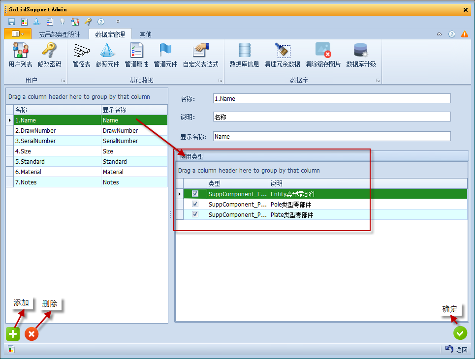
(2) Complete the part information in the custom expressions of the part.
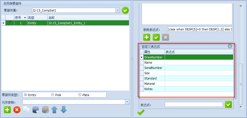
After entering the hanger database management module, click Database Management on the menu bar, click Database Information on the Database toolbar, and complete the database information in the dialog box.
Omitted.
Omitted.
Omitted.
Switch theme skins to change the software's appearance.
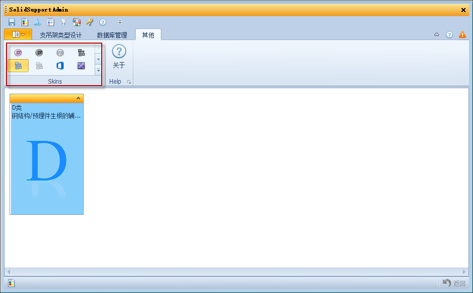
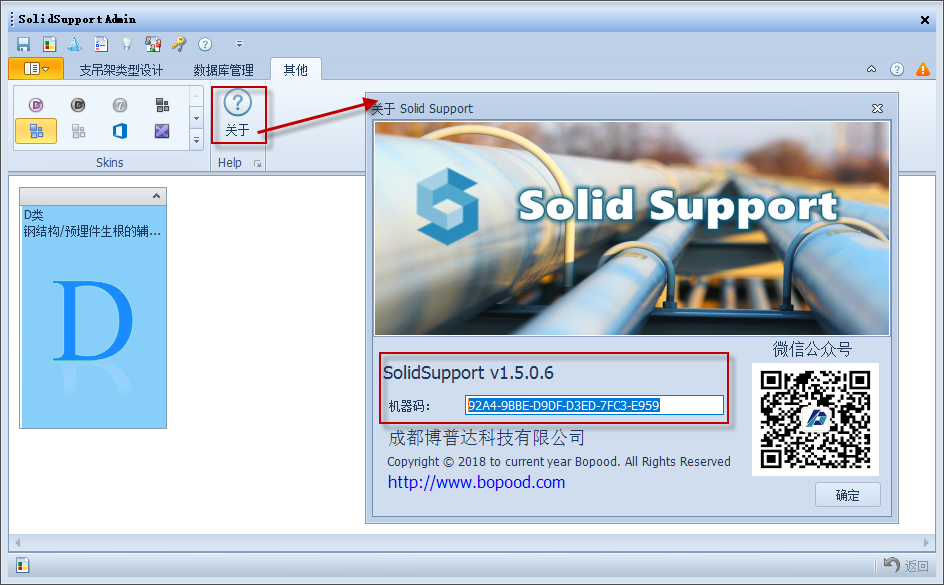
View the software version, machine code, and other information
(1) Piping Property Keywords
See Section 5.2.3, Piping Properties.
(2) Hanger Keywords
| Keyword | Description | Value Type |
|---|---|---|
| param[x] | Hanger subtype parameter | Numeric |
| note[x] | Hanger subtype note | String |
| desp[x] | Input numeric parameter / input text parameter | Numeric / string |
| desp[x,y] | Subtype linked list parameter / expression list parameter | Numeric / string |
| ratt[x] | Reference support parameter | Numeric |
(3) Reference Support Keywords
| Property Type | Keyword | Description | Value Type |
|---|---|---|---|
| General (1) | rpar[x] | Subtype parameter of the reference support | Numeric |
| rdes[x] | Input numeric parameter / input text parameter of the reference support | Numeric / string | |
| rdes[x,y] | Subtype linked list parameter / expression list parameter of the reference support | Numeric / string | |
| Entity② (whole part) |
comp[x].mate | Part material description | String |
| comp[x].posx | X coordinate | Numeric | |
| comp[x].posy | Y coordinate | Numeric | |
| comp[x].posy | Z coordinate | Numeric | |
| Plate② (plate part) |
comp[x].mate | Part material description | String |
| comp[x].posx | X coordinate | Numeric | |
| comp[x].posy | Y coordinate | Numeric | |
| comp[x].posy | Z coordinate | Numeric | |
| comp[x].length | Length | Numeric | |
| comp[x].width | Width | Numeric | |
| Pole② (rod) |
comp[x].mate | Part material description | String |
| comp[x].possx | Start X coordinate | Numeric | |
| comp[x].possy | Start Y coordinate | Numeric | |
| comp[x].possz | Start Z coordinate | Numeric | |
| comp[x].posex | End X coordinate | Numeric | |
| comp[x].posey | End Y coordinate | Numeric | |
| comp[x].posez | End Z coordinate | Numeric | |
| comp[x].angle | Rotation angle | Numeric | |
| Note (1): For general properties, x is the parameter index. Note (2): For part properties, x is the part number. Note (3): Reference support properties can only be used in the property expressions of a reference support. |
(4) Operators
| Operator | Symbol | Description |
|---|---|---|
| Addition | + | Addition operation |
| Subtraction | - | Subtraction operation |
| Multiplication | * | Multiplication operation |
| Division | / | Division operation |
| Concatenation | || | String concatenation |
(5) Functions
| Function | Description |
|---|---|
| abs(x) | Returns the absolute value of numeric parameter x. If x is a string that cannot be converted to a number, returns 0. |
| length(x) | If parameter x is a string, returns the number of characters; if it is numeric, returns the length of its string representation. |
| lower(x) | Returns function parameter x in lowercase. By default, this function applies to ASCII characters only. |
| ltrim(x[,y]) | If optional parameter y is omitted, removes all spaces from the left side of parameter x. If y is given, removes any characters from the left side of x that appear in y. Returns the resulting string. |
| max(x,y,...) | Returns the largest of the function arguments. |
| min(x,y,...) | Returns the smallest of the function arguments. |
| replace(x,y,z) | Replaces all occurrences of substring y in string parameter x with string z and returns the resulting string; the source string x is unchanged. |
| round(x [,y]) | Returns numeric parameter x rounded to y decimal places; if parameter y is omitted, the default is 0. |
| rtrim(x[,y]) | If optional parameter y is omitted, removes all spaces from the right side of parameter x. If y is given, removes any characters from the right side of x that appear in y. Returns the resulting string. |
| substr(x,y[,z]) | Returns a substring of function parameter x, starting at position y (the first character in x is position 1) and z characters long. If z is omitted, returns all characters after the y-th character. If z is negative, returns abs(z) characters to the left starting from position y. If y is negative, counting starts from the end of x up to position abs(y). |
| trim(x[,y]) | If optional parameter y is omitted, removes all spaces from both sides of parameter x. If y is given, removes any characters from both sides of x that appear in y. Returns the resulting string. |
| upper(x) | Returns function parameter x in uppercase. By default, this function applies to ASCII characters only. |
| floor(x) | Returns the integer part of numeric parameter x. |
| sin(x) | Sine function; parameter x is in radians. Example: to calculate the sine of 30 degrees, use sin(30 * pi() / 180). |
| cos(x) | Cosine function; parameter x is in radians. |
| tan(x) | Tangent function; parameter x is in radians. |
| atan(x) | Arctangent function; parameter x is in radians. |
| pi() | Returns the constant pi. |
The coordinate axis mode of a hanger affects the model orientation during hanger assembly. It is influenced by two factors: the piping restriction and the part set positioning method. The following describes it in detail for the hanger database management module and the hanger design module. The hanger types used in the examples are taken from Pipe Support Standard Drawings (HG/T 21629-2021).
| Positioning Method | Description | Characteristics | Applicable Hangers |
|---|---|---|---|
| General | General positioning method | When the piping restriction is Free or Horizontal, the -X direction of the hanger axis is the inlet of the pipe/straight-through fitting, and the X direction is the outlet. When the pipe is judged horizontal, the Z direction matches the Z direction of the world coordinates. When the piping restriction is Vertical, the Z direction of the hanger axis matches the Z direction of the world coordinates and coincides with the centerline of the pipe flow direction. |
Pipe shoes, hangers, structural steel supports, etc. |
| World | World orientation positioning method | The hanger coordinate system is independent of the pipe/fitting and always matches the world X, Y, and Z directions. | Not recommended |
| Elbow90 | 90-degree elbow positioning method | The X and Y directions of the hanger coordinate system match the inlet and outlet directions of the 90-degree elbow. The X direction is always the horizontal end of the elbow; when the pipe is judged horizontal, the Z direction matches the Z direction of the world coordinates. | Elbow trunnions, elbow hangers, elbow supports, etc. |
(1) General positioning method
Positioning method:
When the piping restriction is Free or Horizontal, the -X direction of the hanger axis is the inlet of the pipe/straight-through fitting, and the X direction is the outlet. When the pipe is judged horizontal, the Z direction matches the Z direction of the world coordinates.
When the piping restriction is Vertical, the Z direction of the hanger axis matches the Z direction of the world coordinates and coincides with the centerline of the pipe flow direction.
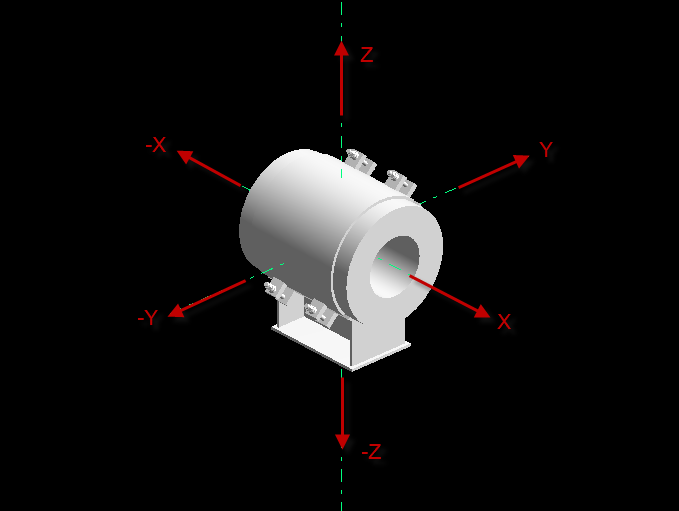
(1) Example 1: L3 cold-insulation pipe shoe with variable height and length (1/2"~72")
Support/Hanger database management module: no piping restriction; the shoe can be added to both horizontal and vertical pipes. The shoe outlet should face the X direction. To reduce the rotation needed when adding the shoe to a horizontal pipe, the saddle should face the -Z direction.
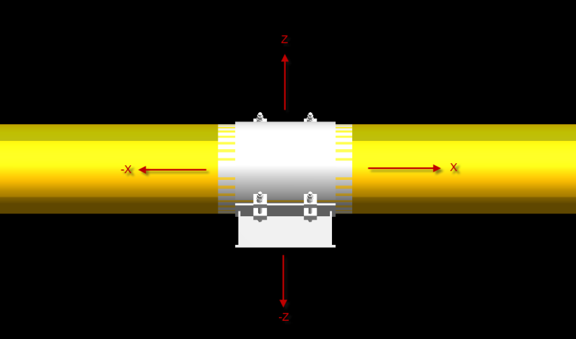
Hanger design module: the result of adding the shoe to a pipe is shown below. The X direction is the pipe flow direction, and the -Z direction is the -Z direction of the world coordinates.
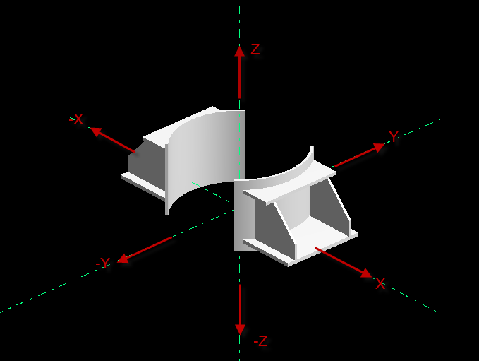
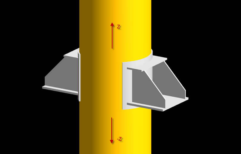
(2) Example 2: F17 lug for risers
Hanger database management module: the piping restriction is vertical pipe. The Z direction of the hanger axis matches the Z direction of the world coordinates and coincides with the centerline of the pipe flow direction. The bearing face of the trunnion should therefore face the -Z direction, and the centerline of the lug should coincide with the pipe axis.
Hanger design module: the result of adding it to a pipe is shown below.
(2)World (World-orientation positioning method)
Positioning method:
The hanger coordinate system is independent of the pipe/fitting and always matches the world X, Y, and Z directions.
No hanger placement example is given.
(3) Elbow90 (90-degree elbow positioning method)
Positioning method:
The X and Y directions of the hanger coordinate system match the inlet and outlet directions of the 90-degree elbow. The X direction is always the horizontal end of the elbow; when the pipe is judged horizontal, the Z direction matches the Z direction of the world coordinates.
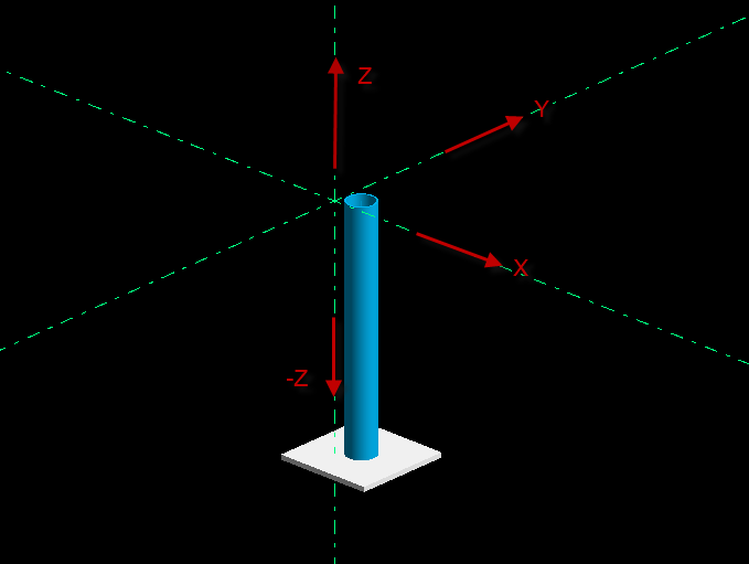
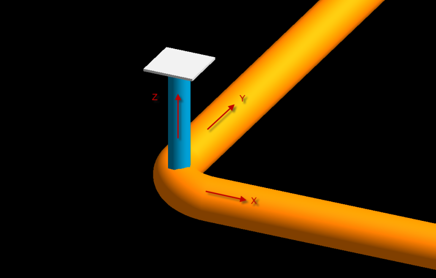
(1) Example 1: F2-H vertical downward trunnion for horizontal elbows
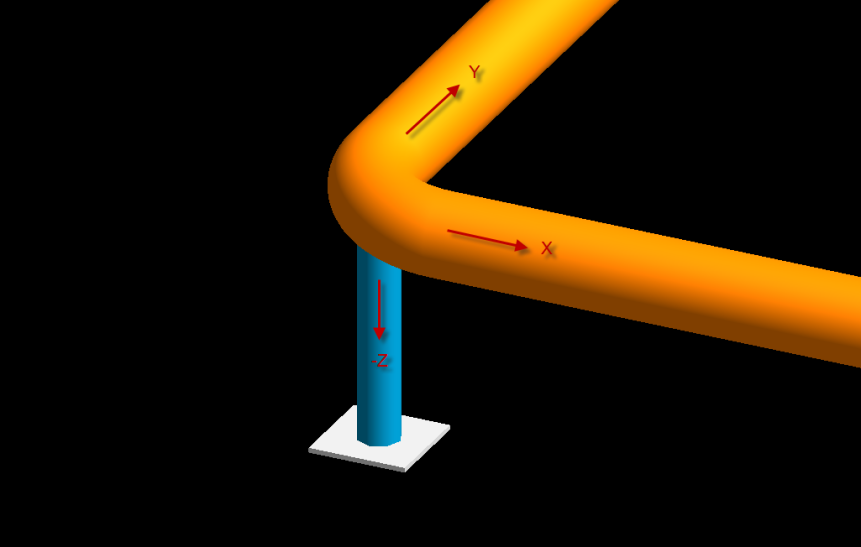
Hanger database management module: imagine a virtual elbow in the hanger coordinate system, with the inlet in the X direction and the outlet in the Y direction. Because the elbow is horizontal, the Z direction matches the Z direction of the world coordinates. The trunnion should face the -Z direction and be offset toward the elbow support point, as shown below.
Hanger design module: the result of adding it to a pipe is shown below. Note that because the elbow is horizontal, the result is the same even if the X and Y directions of the pipe flow are swapped.
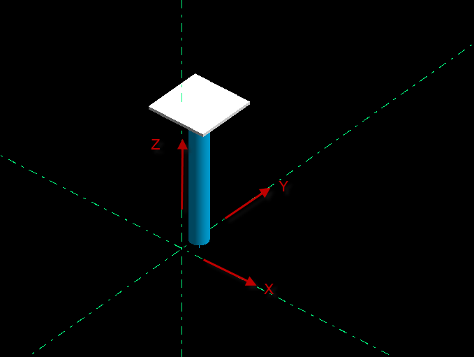
(2) Example 2: F2-H-UP vertical upward trunnion for horizontal elbows
Hanger database management module: imagine a virtual elbow in the hanger coordinate system, with the inlet in the X direction and the outlet in the Y direction. Because the elbow is horizontal, the Z direction matches the Z direction of the world coordinates. The trunnion should face the Z direction and be offset toward the elbow support point, as shown below.
Hanger design module: the result of adding it to a pipe is shown below. Note that because the elbow is horizontal, the result is the same even if the X and Y directions of the pipe flow are swapped.
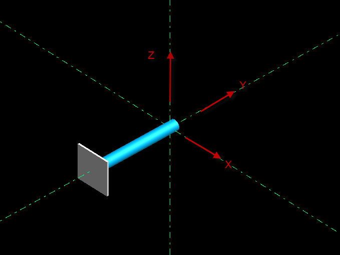
(3) Example 3: F2-V vertical downward trunnion for vertical elbows
Hanger database management module: imagine a virtual elbow in the hanger coordinate system, with the inlet in the X direction and the outlet in the Y direction. Because this is a vertical downward trunnion for a vertical elbow and the X direction is always the horizontal end of the elbow, the vertical end of the elbow lies in the Y direction, so the trunnion direction should be -Y, as shown below.
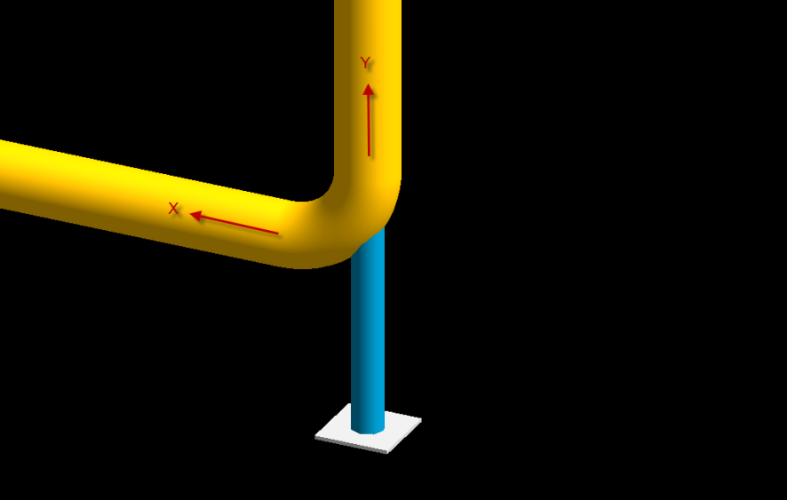
Hanger design module: the result of adding it to a pipe is shown below. Note that because the elbow is vertical, the horizontal end of the elbow is the X direction of the hanger coordinate system.
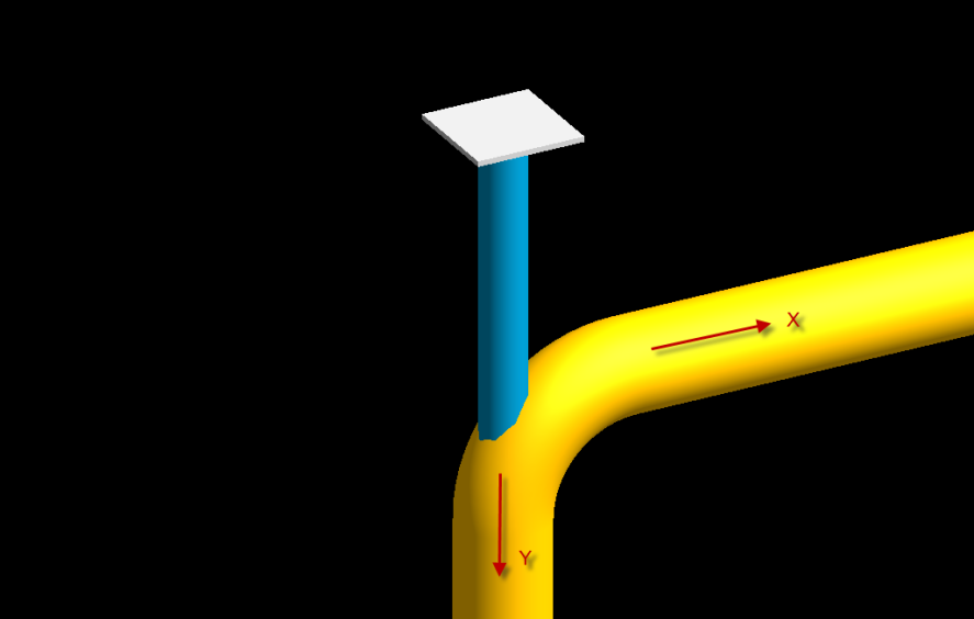
(4) Example 4: F2-V-UP vertical upward trunnion for vertical elbows
Hanger database management module: imagine a virtual elbow in the hanger coordinate system, with the inlet in the X direction and the outlet in the Y direction. Because this is a vertical trunnion for a vertical elbow and the X direction is always the horizontal end of the elbow, the vertical end of the elbow lies in the Y direction, so the trunnion direction should be -Y, as shown below.
Hanger design module: the result of adding it to a pipe is shown below. Note that because the elbow is vertical, the horizontal end of the elbow is the X direction of the hanger coordinate system.
(5) Example 5: F4 horizontal trunnion for vertical elbows
Hanger database management module: imagine a virtual elbow in the hanger coordinate system, with the inlet in the X direction and the outlet in the Y direction. Because this is a horizontal trunnion and the X direction is always the horizontal end of the elbow, the trunnion direction should be -X, as shown below.
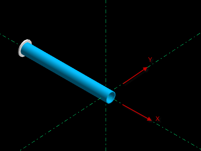
Hanger design module: the result of adding it to a pipe is shown below. Note that because the elbow is vertical, the horizontal end of the elbow is the X direction of the hanger coordinate system.
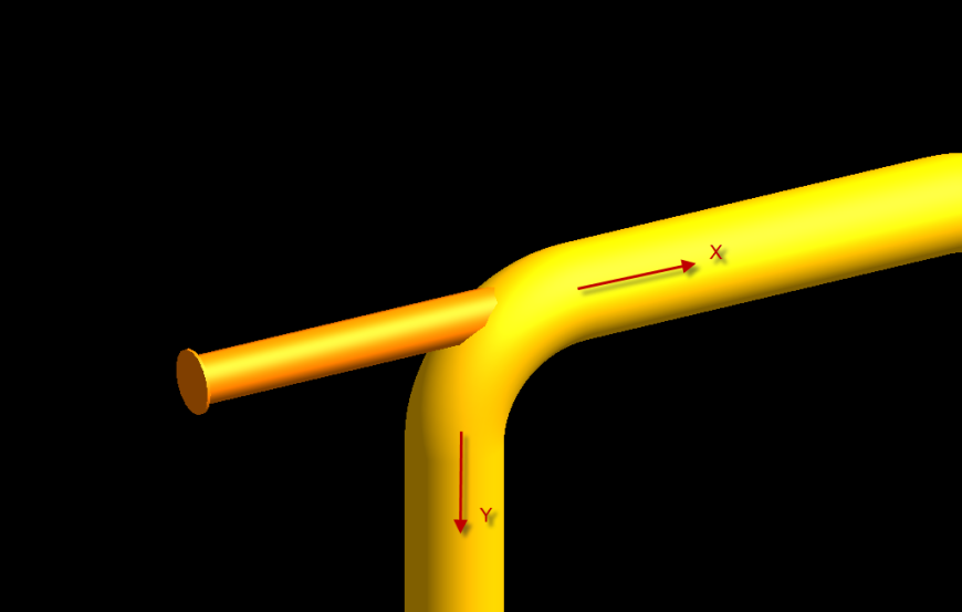
(6) Example 6: F5 horizontal trunnion for horizontal elbows
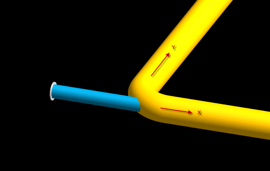
Hanger database management module: imagine a virtual elbow in the hanger coordinate system, with the inlet in the X direction and the outlet in the Y direction. Because this is a horizontal trunnion and the X direction is always the horizontal end of the elbow, the trunnion direction should be -X, as shown below.
Hanger design module: the result of adding it to a pipe is shown below. Note that because the elbow is horizontal, the hanger orientation also changes when the X and Y directions of the pipe flow are swapped.